02 · Your selected option · ST-01
Single LED backdrop
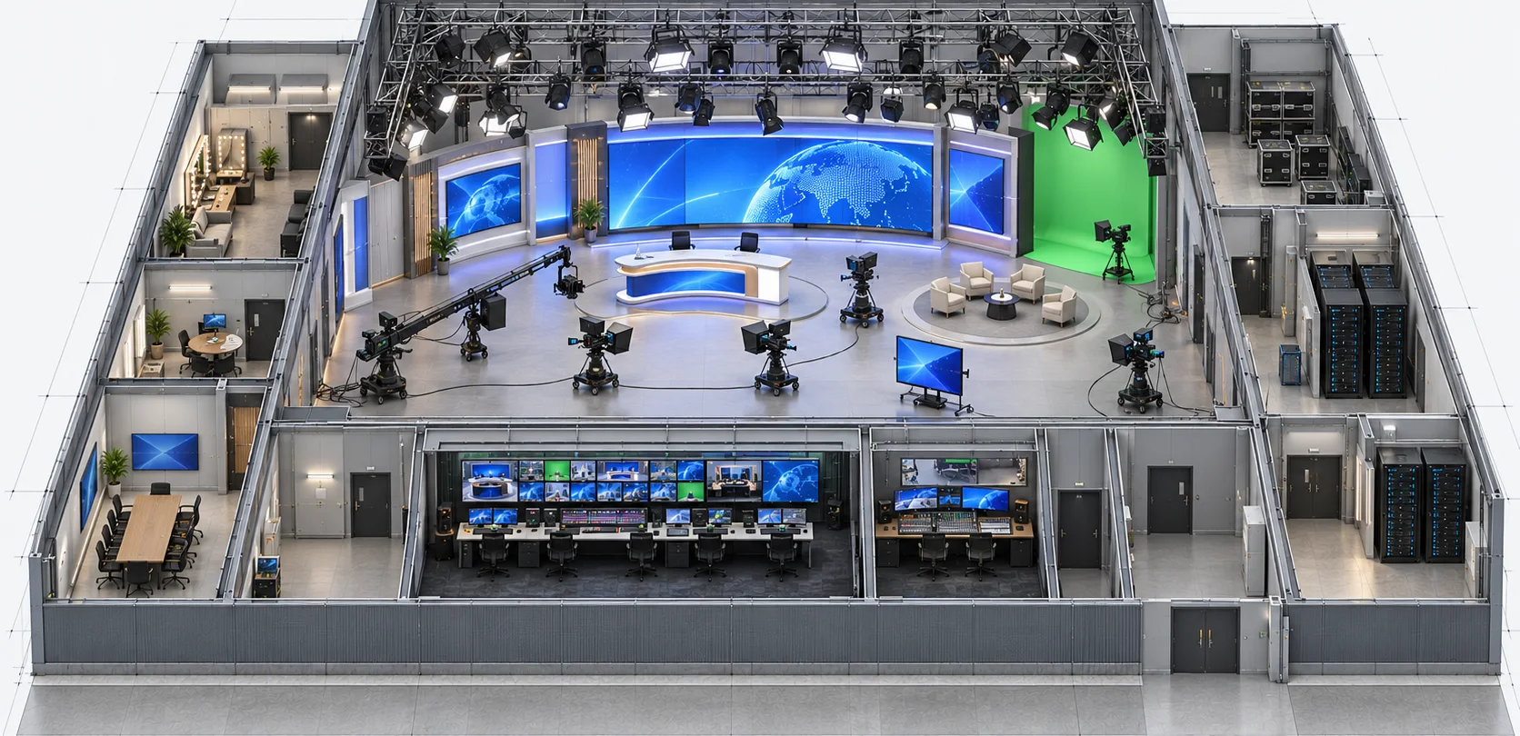
A presenter or interview uses one LED background fed by one content source. The example has one processor, one video distribution amplifier, one selectable monitor, one control workstation and one management switch. Studio reference, working cameras, lighting and a camera return are supplied at agreed interfaces.
Reference design · project selection and system tests required. Read the full design notes →
How it works · functional groups
Check one LED backdrop through the working camera
Background content
Content system
One prepared video output.
Distribution + processor
Matched processing and receiver platform.
LED backdrop
One example 1920 × 1080 surface.
Camera check
Actual studio scene
LED image under the working light.
Camera and routing
Use intended lens and camera settings.
Confidence monitor
Compare camera return with the direct source.
Reference timing reaches the source, processor and camera. A direct signal path provides no automatic recovery from source or processor failure.
Devices & connections Inspect here
What these groups contain Devices and connection references
Rows explain related paths. A group can include parallel outputs; the full drawing shows individual devices, directions and conditions. Repeated IDs refer to the same equipment.
Background content
- Content system
SRC · SRC · Content system ×1 · SDI out + reference in
- Distribution + processor
DA · DA · 3G-SDI DA ×1 · 1 input / 2 outputs
PROC · PROC · LED processor ×1 · One compatible receiver platform
- LED backdrop
LED · LED · One backdrop · 16 cabinets / 16 included receivers · 1920 × 1080 px example
Connections: L01, L02, L03.
Camera check
- Actual studio scene
LED · LED · One backdrop · 16 cabinets / 16 included receivers · 1920 × 1080 px example
LIGHT · LIGHT · Studio lighting ×1 set
- Camera and routing
CAM · CAM · Studio camera ×1 · Working lens and settings
RETURN · RETURN · Existing studio routing ×1 set · One selected camera return
- Confidence monitor
MON · MON · Video monitor ×1 · 2 selectable SDI inputs
Connections: L04, L05, L06, L07.
Other devices, controls and supporting services
- GEN · GEN · Existing reference ×1 interface · Optional new generator replaces this
- REFDA · REFDA · Reference DA ×1 · 1 in / 4 out; 3 outputs used
- PC · PC · Operator workstation ×1 · Includes UI display; check camera return
- NET · NET · Management switch ×1 · 3 of at least 8 ports used
ST-01 · Single LED backdrop
One content feed reaches the backdrop; the operator checks both the feed and camera return.
Signal flow
All 6 connections · 7 devices and services
Choose a connection to read its endpoints, direction and interface. Repeated device IDs refer to the same equipment across views.
From · SRCSRC · Content system ×1 SDI out + reference in
To · DADA · 3G-SDI DA ×1 1 input / 2 outputs
Direction: source → destination · 1080p60 SDI
From · DADA · 3G-SDI DA ×1 1 input / 2 outputs
To · PROCPROC · LED processor ×1 One compatible receiver platform
Direction: source → destination · SDI output 1
From · PROCPROC · LED processor ×1 One compatible receiver platform
To · LEDLED · One backdrop 16 cabinets / 16 included receivers 1920 × 1080 px example
Direction: source → destination · 4 LED data chains 4 cabinets per chain
From · CAMCAM · Studio camera ×1 Working lens and settings
To · RETURNRETURN · Existing studio routing ×1 set One selected camera return
Direction: source → destination · Existing studio video path
From · RETURNRETURN · Existing studio routing ×1 set One selected camera return
To · MONMON · Video monitor ×1 2 selectable SDI inputs
Direction: source → destination · SDI camera return / input 2
From · DADA · 3G-SDI DA ×1 1 input / 2 outputs
To · MONMON · Video monitor ×1 2 selectable SDI inputs
Direction: source → destination · SDI output 2 / input 1
SRC · SRC · Content system ×1 SDI out + reference in
Connections: L01. Repeated device IDs refer to the same equipment.
DA · DA · 3G-SDI DA ×1 1 input / 2 outputs
Connections: L01, L02, L08. Repeated device IDs refer to the same equipment.
PROC · PROC · LED processor ×1 One compatible receiver platform
Connections: L02, L03. Repeated device IDs refer to the same equipment.
LED · LED · One backdrop 16 cabinets / 16 included receivers 1920 × 1080 px example
Connections: L03. Repeated device IDs refer to the same equipment.
CAM · CAM · Studio camera ×1 Working lens and settings
Connections: L05. Repeated device IDs refer to the same equipment.
RETURN · RETURN · Existing studio routing ×1 set One selected camera return
Connections: L05, L06. Repeated device IDs refer to the same equipment.
MON · MON · Video monitor ×1 2 selectable SDI inputs
Connections: L06, L08. Repeated device IDs refer to the same equipment.
Devices, connections & design conditions 6 connections
- One content feed reaches the backdrop; the operator checks both the feed and camera return.
- ST-01 functional diagram showing SDI distribution, one LED processor, LED data, studio reference and separate management routes.
- SRC
- SRC · Content system ×1 SDI out + reference in
- DA
- DA · 3G-SDI DA ×1 1 input / 2 outputs
- PROC
- PROC · LED processor ×1 One compatible receiver platform
- LED
- LED · One backdrop 16 cabinets / 16 included receivers 1920 × 1080 px example
- CAM
- CAM · Studio camera ×1 Working lens and settings
- RETURN
- RETURN · Existing studio routing ×1 set One selected camera return
- MON
- MON · Video monitor ×1 2 selectable SDI inputs
- SRC → DA1080p60 SDI
- DA → PROCSDI output 1
- PROC → LED4 LED data chains 4 cabinets per chain
- CAM → RETURNExisting studio video path
- RETURN → MONSDI camera return / input 2
- DA → MONSDI output 2 / input 1
Control & status
All 3 connections · 4 devices and services
Choose a connection to read its endpoints, direction and interface. Repeated device IDs refer to the same equipment across views.
From · PCPC · Operator workstation ×1 Includes UI display; check camera return
To · NETNET · Management switch ×1 3 of at least 8 ports used
Bidirectional · Ethernet commands / status
From · NETNET · Management switch ×1 3 of at least 8 ports used
To · SRCSRC · Content system ×1 SDI out + reference in
Bidirectional · Management Ethernet
From · NETNET · Management switch ×1 3 of at least 8 ports used
To · PROCPROC · LED processor ×1 One compatible receiver platform
Bidirectional · Management Ethernet
SRC · SRC · Content system ×1 SDI out + reference in
Connections: L14. Repeated device IDs refer to the same equipment.
PROC · PROC · LED processor ×1 One compatible receiver platform
Connections: L15. Repeated device IDs refer to the same equipment.
PC · PC · Operator workstation ×1 Includes UI display; check camera return
Connections: L13. Repeated device IDs refer to the same equipment.
NET · NET · Management switch ×1 3 of at least 8 ports used
Connections: L13, L14, L15. Repeated device IDs refer to the same equipment.
Devices, connections & design conditions 3 connections
- One content feed reaches the backdrop; the operator checks both the feed and camera return.
- ST-01 functional diagram showing SDI distribution, one LED processor, LED data, studio reference and separate management routes.
- SRC
- SRC · Content system ×1 SDI out + reference in
- PROC
- PROC · LED processor ×1 One compatible receiver platform
- PC
- PC · Operator workstation ×1 Includes UI display; check camera return
- NET
- NET · Management switch ×1 3 of at least 8 ports used
- PC ↔ NETEthernet commands / status
- NET ↔ SRCManagement Ethernet
- NET ↔ PROCManagement Ethernet
Timing & camera check
All 6 connections · 7 devices and services
Choose a connection to read its endpoints, direction and interface. Repeated device IDs refer to the same equipment across views.
From · LIGHTLIGHT · Studio lighting ×1 set
To · CAMCAM · Studio camera ×1 Working lens and settings
Direction: source → destination · Working light scene
From · LEDLED · One backdrop 16 cabinets / 16 included receivers 1920 × 1080 px example
To · CAMCAM · Studio camera ×1 Working lens and settings
Direction: source → destination · Optical image
From · GENGEN · Existing reference ×1 interface Optional new generator replaces this
To · REFDAREFDA · Reference DA ×1 1 in / 4 out; 3 outputs used
Direction: source → destination · 75-ohm reference
From · REFDAREFDA · Reference DA ×1 1 in / 4 out; 3 outputs used
To · SRCSRC · Content system ×1 SDI out + reference in
Direction: source → destination · Tri-level reference
From · REFDAREFDA · Reference DA ×1 1 in / 4 out; 3 outputs used
To · PROCPROC · LED processor ×1 One compatible receiver platform
Direction: source → destination · Tri-level reference
From · REFDAREFDA · Reference DA ×1 1 in / 4 out; 3 outputs used
To · CAMCAM · Studio camera ×1 Working lens and settings
Direction: source → destination · Tri-level reference
SRC · SRC · Content system ×1 SDI out + reference in
Connections: L10. Repeated device IDs refer to the same equipment.
PROC · PROC · LED processor ×1 One compatible receiver platform
Connections: L11. Repeated device IDs refer to the same equipment.
LED · LED · One backdrop 16 cabinets / 16 included receivers 1920 × 1080 px example
Connections: L07. Repeated device IDs refer to the same equipment.
CAM · CAM · Studio camera ×1 Working lens and settings
Connections: L04, L07, L12. Repeated device IDs refer to the same equipment.
LIGHT · LIGHT · Studio lighting ×1 set
Connections: L04. Repeated device IDs refer to the same equipment.
GEN · GEN · Existing reference ×1 interface Optional new generator replaces this
Connections: L09. Repeated device IDs refer to the same equipment.
REFDA · REFDA · Reference DA ×1 1 in / 4 out; 3 outputs used
Connections: L09, L10, L11, L12. Repeated device IDs refer to the same equipment.
Devices, connections & design conditions 6 connections
- One content feed reaches the backdrop; the operator checks both the feed and camera return.
- ST-01 functional diagram showing SDI distribution, one LED processor, LED data, studio reference and separate management routes.
- SRC
- SRC · Content system ×1 SDI out + reference in
- PROC
- PROC · LED processor ×1 One compatible receiver platform
- LED
- LED · One backdrop 16 cabinets / 16 included receivers 1920 × 1080 px example
- CAM
- CAM · Studio camera ×1 Working lens and settings
- LIGHT
- LIGHT · Studio lighting ×1 set
- GEN
- GEN · Existing reference ×1 interface Optional new generator replaces this
- REFDA
- REFDA · Reference DA ×1 1 in / 4 out; 3 outputs used
- LIGHT → CAMWorking light scene
- LED → CAMOptical image
- GEN → REFDA75-ohm reference
- REFDA → SRCTri-level reference
- REFDA → PROCTri-level reference
- REFDA → CAMTri-level reference
Typical architecture · not a project drawing
03 · Scope & limits
What is included. What needs agreement.
Operation and equipment
The source feeds the processor and the confidence monitor. The operator selects a saved display setup, checks the reference and input status, and compares the rendered background with the camera return under the approved light scene.
Equipment schedule · 10 groups
Example quantities, not an approved procurement schedule. Catalogue links provide component specifications; they do not confirm system compatibility or availability.
- LED surface assemblies with matched receivers
- 1
LED display equipment
LED display equipment → - LED processors
- 1
LED processing equipment
LED processing equipment → - Compatible LED distribution units
- Direct connection
Selected with the complete processing platform
- Content systems / independent video outputs
- 1 / 1
Playback, output hardware and licences by design
- Video distribution amplifiers
- 1
Interface and format checked against the signal schedule
- Video monitors
- 1
At least 2 selectable inputs
- Control workstation / management switch
- 1 / 1
Commands, status and local access by design
- Reference infrastructure
- Existing reference and 1 distribution unit
Counted once per selected studio design
- Protected equipment power branches
- 1
Runtime and upstream separation by electrical design
- Installation and service provision
- 1 studio set
Structure, LED power, cables, cooling and spares itemised for the site
What we need to demonstrate
Before testing, agree the cameras, lenses, frame rates, shutter settings, shot positions, LED brightness, lighting scenes and representative content. Record the versions and receiver configuration. Review dark tones, gradients, motion and fine detail in both wide and close shots; agree the acceptable image with the camera team. ST-01 checks one complete content-to-camera path. ST-02 adds simultaneous distinct images, preset recall and shots spanning the three surfaces. ST-03 adds the agreed source, processor, cable, distribution and reference failures, with time-stamped observations of interruption, recovery and operator status. Uncovered failures are recorded alongside covered ones. The handover includes pixel maps, content profiles, signal and port schedules, calibrated settings, software versions, test clips and an operating guide. A camera or firmware change can require part of the acceptance programme to be repeated..
Handover evidence: Agreed criteria, equipment and version schedule, measured test results and recovery procedure..
These are planned project checks. The reference configuration has not passed physical system acceptance.
Discuss this option · ST-01