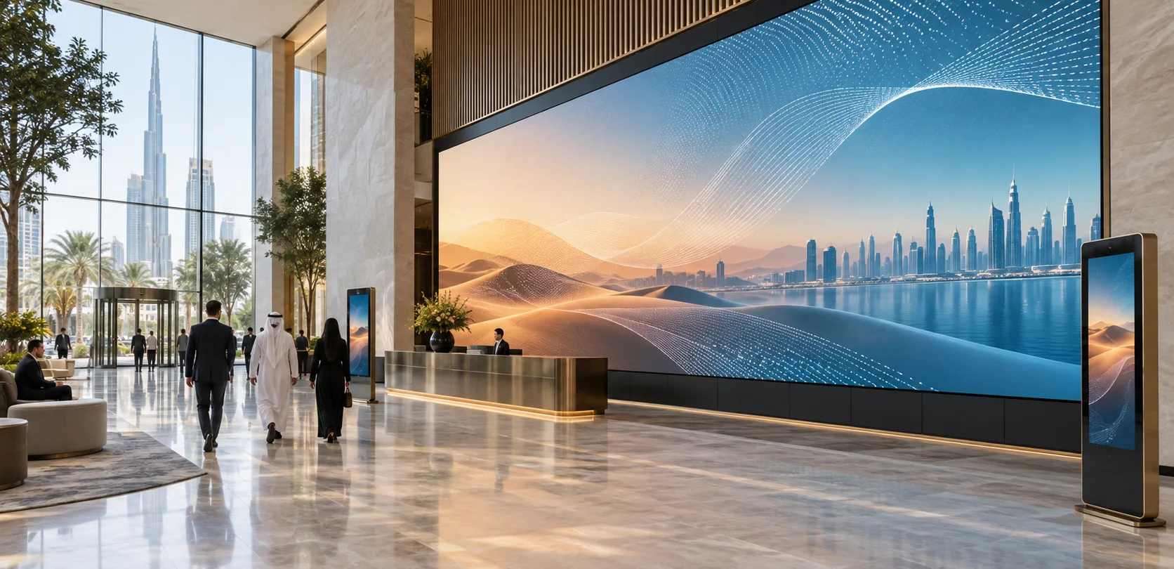
Concept visualisation of an integrated digital signage and LED display environment in Dubai
Solution 04 / 10

AV systems integration · Dubai & the UAE

Digital signage & retail displays

The right message, on the right screen.

Publish the right information across one screen or a managed display network.

  • Consultation
  • Design
  • Integration
  • Support
From the brief
to a working system
See how
it works
  • The right message

    Start with content, timing and audience.

  • One or many screens

    Match management to the display network.

  • Planned publishing

    Agree schedules and ownership of content.

  • Managed access

    Define publishing and support roles.

01 · Choose a starting point

What does your team need to do?

Typical configurations, not fixed packages or completed projects. Each needs validation against your users, sources, operating conditions and site.

02 · Your selected option · DS-01

Single information screen

A staff member updates notices and short videos at one indoor entrance, reception or counter.

Change option ↑

Reference design · project selection and system tests required. Read the full design notes →

How it works · functional groups

Publish a reviewed package to one screen

Local update

Staff computer

Prepare content and schedule; write the storage card.

Local player

Insert the reviewed card and start playback.

Information screen

Staff visually check the release.

This is a local update workflow. A playback picture is checked by staff; it is not a remote CMS health report.

Devices & connections Inspect here
What these groups contain Devices and connection references

Rows explain related paths. A group can include parallel outputs; the full drawing shows individual devices, directions and conditions. Repeated IDs refer to the same equipment.

Local update

Staff computer

PC · 1 staff computer · Local authoring + schedule

READER · 1 microSD reader · Staff update procedure

CARD · 1 storage card · Reviewed local package

Local player

PLAYER · 1 standard player · Local playback + clock

Information screen

DISPLAY · 1 commercial display · Indoor information point

Connections: L01, L02, L03, L04.

Other devices, controls and supporting services

  • POWER · Local power · Player DC + display AC

DS-01 · Single information screen

One locally maintained information screen.

Signal flow

Signal flow. Devices, connections and conditions follow the drawing.Open SVG ↗
DS-01 · Signal flowReference configuration. One staff computer writes one storage card for one player. HDMI feeds one display. Staff check the visible result. No network or cloud service is required in the base design. Repeated device identifiers refer to the same equipment across views. Equipment illustrations are schematic; labels define quantities.{"sourceHash":"afc0e3d16032d2adc425979d59a876ce1f11919dfc3d352a2ef694c9f1d145f4","view":"signal","nodes":["PC","READER","CARD","PLAYER","DISPLAY"],"edges":["L01","L02","L03","L04"]}PIXEL COMMAND SOLUTIONS / DS-01 / SIGNAL FLOWSignal flowREFERENCE DESIGN · PROJECT VALIDATION REQUIREDPC → READER: USB file transferUSB file transferREADER → CARD: Write filesWrite filesCARD → PLAYER: Insert into playerInsert into playerPLAYER → DISPLAY: 1 HDMI video link1 HDMI video link1 staff computer Local authoring + schedulePC1 staff computer1 microSD reader Staff update procedureREADER1 microSD reader1 storage card Reviewed local packageCARD1 storage card1 standard player Local playback + clockPLAYER1 standard player1 commercial display Indoor information pointDISPLAY1 commercial displayUSB / KVMNetwork / dataVideo / LED data
Devices, connections & design conditions 4 connections
  • One locally maintained information screen.
  • An editor prepares a storage card for one player, which sends HDMI video to one display. Staff verify the visible result.
PC
1 staff computer Local authoring + schedule
READER
1 microSD reader Staff update procedure
CARD
1 storage card Reviewed local package
PLAYER
1 standard player Local playback + clock
DISPLAY
1 commercial display Indoor information point
  1. PC → READERUSB file transfer
  2. READER → CARDWrite files
  3. CARD → PLAYERInsert into player
  4. PLAYER → DISPLAY1 HDMI video link

Control & power

Signal flow. Devices, connections and conditions follow the drawing.Open SVG ↗
DS-01 · Control & powerReference configuration. One staff computer writes one storage card for one player. HDMI feeds one display. Staff check the visible result. No network or cloud service is required in the base design. Repeated device identifiers refer to the same equipment across views. Equipment illustrations are schematic; labels define quantities.{"sourceHash":"afc0e3d16032d2adc425979d59a876ce1f11919dfc3d352a2ef694c9f1d145f4","view":"control","nodes":["PC","PLAYER","DISPLAY","POWER"],"edges":["L05","L06","L07"]}PIXEL COMMAND SOLUTIONS / DS-01 / CONTROL & POWERControl & powerREFERENCE DESIGN · PROJECT VALIDATION REQUIREDDISPLAY → PC: Staff visually check releaseStaff visually checkreleasePOWER → PLAYER: PowerPowerPOWER → DISPLAY: PowerPower1 staff computer Local authoring + schedulePC1 staff computer1 standard player Local playback + clockPLAYER1 standard player1 commercial display Indoor information pointDISPLAY1 commercial displayLocal power Player DC + display ACPOWERLocal powerControl / statusPower
Devices, connections & design conditions 3 connections
  • One locally maintained information screen.
  • An editor prepares a storage card for one player, which sends HDMI video to one display. Staff verify the visible result.
PC
1 staff computer Local authoring + schedule
PLAYER
1 standard player Local playback + clock
DISPLAY
1 commercial display Indoor information point
POWER
Local power Player DC + display AC
  1. DISPLAY → PCStaff visually check release
  2. POWER → PLAYERPower
  3. POWER → DISPLAYPower

Typical architecture · not a project drawing

03 · Scope & limits

What is included. What needs agreement.

System composition

One commercial HDMI display, one external player, one local storage card, a mounting set, an HDMI connection and local power. An existing staff computer with a card reader prepares and transfers the presentation. The base workflow uses removable media; local network publishing is an optional alternative.

Equipment schedule · 5 groups

Example quantities, not an approved procurement schedule. Catalogue links provide component specifications; they do not confirm system compatibility or availability.

Commercial displays
1

Operating hours, brightness, orientation, service access and real-content readability · DS-01/02/03

Media players and local storage
1 player / 1 card

HDMI output, supported media, content capacity and recovery behaviour · DS-01/02/03

Content publishing software
1 local authoring installation; no cloud subscription

Local authoring or managed endpoint entitlements, roles, groups and licence term · Local authoring in DS-01; CMS in DS-02/03

Mounting, cabling and power
1 installation set

Site routes, device connections, ventilation and maintenance access · All; lengths and electrical loads determined during design

Network and service infrastructure
Optional network; local authoring uses the existing staff computer

Port capacity, firewall rules, backups and operational ownership · Shared per deployment; DS-01 network optional

Browse equipment specifications →

What we need to demonstrate

Load approved content, read it at the intended position, check the schedule and restart after power loss.

Handover evidence: Content/version record, display check and local update guide.

These are planned project checks. The reference configuration has not passed physical system acceptance.

Discuss this option · DS-01

02 · Your selected option · DS-02

Managed six-screen network

An office or store needs different campaigns for three locations, with two screens in each content group.

Change option ↑

Reference design · project selection and system tests required. Read the full design notes →

How it works · functional groups

Schedule campaigns across six screens

Managed publishing

Editor + CMS

Named roles approve content and schedules.

Six players

Approved outbound network access; local saved media.

Three locations

Two independent screens in each location.

Players request content and report status through the same network. Six active players need six entitlements; service terms and behaviour during an outage must be agreed.

Devices & connections Inspect here
What these groups contain Devices and connection references

Rows explain related paths. A group can include parallel outputs; the full drawing shows individual devices, directions and conditions. Repeated IDs refer to the same equipment.

Managed publishing

Editor + CMS

EDITOR · 1 editor workstation · Named editor / publisher / admin accounts

CMS · 1 CMS workspace · Library, schedules and player reports

RIGHTS · 6 CMS endpoint entitlements · Roles and service term to confirm

Six players

FIREWALL · Site firewall + uplink · Approved outbound service access

SWITCH · 1 managed 16-port switch · 8 ports used in base

PLAYERS · 6 standard players · A: P01-02 / B: P03-04 / C: P05-06

CARDS · 6 local storage cards · Saved media + schedule

Three locations

DISPLAYS · 6 commercial displays · One HDMI input per screen

Connections: L01, L03, L04, L06, L07, L08.

Other devices, controls and supporting services

  • POWER · Local power at each point · Player DC + display AC; no endpoint PoE

DS-02 · Managed six-screen network

Six players receive schedules for three content groups.

Signal flow

Signal flow. Devices, connections and conditions follow the drawing.Open SVG ↗
DS-02 · Signal flowReference configuration. One editor workstation accesses one CMS workspace with six endpoint entitlements. Six players fetch content through the site firewall and switch, and return status by the same route. Each player has a local storage card and HDMI display. Groups A, B and C each contain two players. Power is local, not PoE. Repeated device identifiers refer to the same equipment across views. Equipment illustrations are schematic; labels define quantities.{"sourceHash":"d6be1593177202d1ef50cf65685251a744bb4f81724af30197a27ab69a061ef4","view":"signal","nodes":["CMS","FIREWALL","SWITCH","PLAYERS","CARDS","DISPLAYS"],"edges":["L03","L04","L06","L07","L08"]}PIXEL COMMAND SOLUTIONS / DS-02 / SIGNAL FLOWSignal flowREFERENCE DESIGN · PROJECT VALIDATION REQUIREDCMS → FIREWALL: HTTPS content replies to player requestsHTTPS content repliesto player requestsFIREWALL → SWITCH: Ethernet uplinkEthernet uplinkSWITCH → PLAYERS: 6 Ethernet access links6 Ethernet access linksCARDS → PLAYERS: One installed card per playerOne installed card perplayerPLAYERS → DISPLAYS: 6 HDMI video links6 HDMI video links1 CMS workspace Library, schedules and player reportsCMS1 CMS workspaceSite firewall + uplink Approved outbound service accessFIREWALLSite firewall + uplink1 managed 16-port switch 8 ports used in baseSWITCH1 managed 16-portswitch6 standard players A: P01-02 / B: P03-04 / C: P05-06PLAYERS6 standard players6 local storage cards Saved media + scheduleCARDS6 local storage cards6 commercial displays One HDMI input per screenDISPLAYS6 commercial displaysNetwork / dataVideo / LED data
Devices, connections & design conditions 5 connections
  • Six players receive schedules for three content groups.
  • Editors access a CMS. Six players use the site network to fetch content and return status; each player feeds one display over HDMI.
CMS
1 CMS workspace Library, schedules and player reports
FIREWALL
Site firewall + uplink Approved outbound service access
SWITCH
1 managed 16-port switch 8 ports used in base
PLAYERS
6 standard players A: P01-02 / B: P03-04 / C: P05-06
CARDS
6 local storage cards Saved media + schedule
DISPLAYS
6 commercial displays One HDMI input per screen
  1. CMS → FIREWALLHTTPS content replies to player requests
  2. FIREWALL → SWITCHEthernet uplink
  3. SWITCH → PLAYERS6 Ethernet access links
  4. CARDS → PLAYERSOne installed card per player
  5. PLAYERS → DISPLAYS6 HDMI video links

Control & power

Signal flow. Devices, connections and conditions follow the drawing.Open SVG ↗
DS-02 · Control & powerReference configuration. One editor workstation accesses one CMS workspace with six endpoint entitlements. Six players fetch content through the site firewall and switch, and return status by the same route. Each player has a local storage card and HDMI display. Groups A, B and C each contain two players. Power is local, not PoE. Repeated device identifiers refer to the same equipment across views. Equipment illustrations are schematic; labels define quantities.{"sourceHash":"d6be1593177202d1ef50cf65685251a744bb4f81724af30197a27ab69a061ef4","view":"control","nodes":["EDITOR","CMS","RIGHTS","SWITCH","PLAYERS","DISPLAYS","POWER"],"edges":["L01","L02","L05","L09","L10","L11"]}PIXEL COMMAND SOLUTIONS / DS-02 / CONTROL & POWERControl & powerREFERENCE DESIGN · PROJECT VALIDATION REQUIREDEDITOR → CMS: CMS console over HTTPS via site networkCMS console over HTTPSvia site networkRIGHTS → CMS: One entitlement per active playerOne entitlement peractive playerEDITOR → SWITCH: 1 Ethernet access port1 Ethernet access portPLAYERS → CMS: Requests and status via same switch and firewallRequests and status viasame switch andfirewallPOWER → PLAYERS: PowerPowerPOWER → DISPLAYS: PowerPower1 editor workstation Named editor / publisher / admin accountsEDITOR1 editor workstation1 CMS workspace Library, schedules and player reportsCMS1 CMS workspace6 CMS endpoint entitlements Roles and service term to confirmRIGHTS6 CMS endpointentitlements1 managed 16-port switch 8 ports used in baseSWITCH1 managed 16-portswitch6 standard players A: P01-02 / B: P03-04 / C: P05-06PLAYERS6 standard players6 commercial displays One HDMI input per screenDISPLAYS6 commercial displaysLocal power at each point Player DC + display AC; no endpoint PoEPOWERLocal power at eachpointControl / statusPower
Devices, connections & design conditions 6 connections
  • Six players receive schedules for three content groups.
  • Editors access a CMS. Six players use the site network to fetch content and return status; each player feeds one display over HDMI.
EDITOR
1 editor workstation Named editor / publisher / admin accounts
CMS
1 CMS workspace Library, schedules and player reports
RIGHTS
6 CMS endpoint entitlements Roles and service term to confirm
SWITCH
1 managed 16-port switch 8 ports used in base
PLAYERS
6 standard players A: P01-02 / B: P03-04 / C: P05-06
DISPLAYS
6 commercial displays One HDMI input per screen
POWER
Local power at each point Player DC + display AC; no endpoint PoE
  1. EDITOR → CMSCMS console over HTTPS via site network
  2. RIGHTS → CMSOne entitlement per active player
  3. EDITOR → SWITCH1 Ethernet access port
  4. PLAYERS → CMSRequests and status via same switch and firewall
  5. POWER → PLAYERSPower
  6. POWER → DISPLAYSPower

Typical architecture · not a project drawing

03 · Scope & limits

What is included. What needs agreement.

System composition

Six commercial displays, six players, six local storage cards and six CMS endpoint entitlements. Shared infrastructure comprises one managed access switch, the site's firewall and internet connection, an existing editor workstation, and one configured CMS workspace. Each player has its own HDMI output and local power supply.

Equipment schedule · 5 groups

Example quantities, not an approved procurement schedule. Catalogue links provide component specifications; they do not confirm system compatibility or availability.

Commercial displays
6

Operating hours, brightness, orientation, service access and real-content readability · DS-01/02/03

Media players and local storage
6 players / 6 cards

HDMI output, supported media, content capacity and recovery behaviour · DS-01/02/03

Content publishing software
6 CMS endpoint entitlements

Local authoring or managed endpoint entitlements, roles, groups and licence term · Local authoring in DS-01; CMS in DS-02/03

Mounting, cabling and power
1 installation set

Site routes, device connections, ventilation and maintenance access · All; lengths and electrical loads determined during design

Network and service infrastructure
1 shared deployment

Port capacity, firewall rules, backups and operational ownership · Shared per deployment; DS-01 network optional

Browse equipment specifications →

What we need to demonstrate

Publish to one group without altering the other two; deny unauthorised actions; interrupt a download; disconnect and restore WAN.

Handover evidence: Group/permissions report, schedule evidence, outage and recovery results.

These are planned project checks. The reference configuration has not passed physical system acceptance.

Discuss this option · DS-02

02 · Your selected option · DS-03

Retail displays, wayfinding & LED

A shopping centre combines eight advertising screens, two visitor navigation kiosks and one LED feature surface.

Change option ↑

Reference design · project selection and system tests required. Read the full design notes →

How it works · functional groups

Coordinate campaigns, wayfinding and an LED surface

Campaigns and LED

Campaign publishing

One CMS workspace; eleven total endpoint entitlements.

Separate playback devices

Eight standard players and one LED player.

Public displays

Eight screens; LED processor maps the additional LED surface.

Visitor wayfinding

Directory and application

Versioned maps and a separately scoped kiosk application.

Two interactive players

Receive directory data and application packages.

Two touch displays

Picture out and USB touch return.

The CMS, directory data and navigation application have separate responsibilities. LED receiver data is not ordinary CMS Ethernet. All eleven players need local power and storage.

Devices & connections Inspect here
What these groups contain Devices and connection references

Rows explain related paths. A group can include parallel outputs; the full drawing shows individual devices, directions and conditions. Repeated IDs refer to the same equipment.

Campaigns and LED

Campaign publishing

STAFF · 2 staff workstations · Campaign publisher / directory editor

CMS · 1 CMS workspace · Library, schedules and player reports

RIGHTS · 11 CMS endpoint entitlements · 8 standard + 2 kiosk + 1 LED

Separate playback devices

FIREWALL · Site firewall + uplink · Approved outbound access

SWITCH · 1 managed 24-port switch · 14 ports used: 11 players + uplink + 2 staff

STANDARD · 8 standard players · P01-P08

LEDPLAYER · 1 LED content player · P11

Public displays

DISPLAYS · 8 commercial displays · Campaigns and information

PROCESSOR · 1 LED processor · Input format and pixel map TBD

SURFACE · 1 LED surface package · Receiving cards, modules and PSU

Connections: L01, L05, L07, L08, L10, L15, L18, L19.

Visitor wayfinding

Directory and application

STAFF · 2 staff workstations · Campaign publisher / directory editor

DIRECTORY · 1 directory data service · Versioned maps + tenant data

APP · 1 navigation application deployment · Runtime rights for 2 kiosks

Two interactive players

SWITCH · 1 managed 24-port switch · 14 ports used: 11 players + uplink + 2 staff

INTERACTIVE · 2 interactive players · P09-P10 / local kiosk application

Two touch displays

TOUCH · 2 touch displays · Search and maps

Connections: L02, L06, L07, L09, L14, L16, L17.

Other devices, controls and supporting services

  • CARDS · 11 local storage cards · One installed in each player
  • POWER · Local DC power for all 11 players · Separate power for displays and LED · No endpoint PoE in this design

DS-03 · Retail displays, wayfinding & LED

Eleven playback endpoints with separate navigation and LED paths.

Signal flow

Signal flow. Devices, connections and conditions follow the drawing.Open SVG ↗
DS-03 · Signal flowReference configuration with eleven independent players and storage cards. Eight standard players feed eight displays. Two interactive players feed two touch displays by HDMI and receive USB touch. One LED player feeds one LED processor and one receiving system. The site switch and firewall carry CMS downloads and status. A separate directory service delivers navigation data. All players use local DC power. Local DC power for all 11 players Separate power for displays and LED No endpoint PoE in this design Repeated device identifiers refer to the same equipment across views. Equipment illustrations are schematic; labels define quantities.{"sourceHash":"41e8b3f875978e7e7eb005b0d8735e22d2b32e4bc27c3003771fdf5623d413f3","view":"signal","nodes":["CMS","DIRECTORY","FIREWALL","SWITCH","CARDS","STANDARD","INTERACTIVE","LEDPLAYER","DISPLAYS","TOUCH","PROCESSOR","SURFACE"],"edges":["L05","L06","L07","L08","L09","L10","L11","L12","L13","L15","L16","L17","L18","L19"]}PIXEL COMMAND SOLUTIONS / DS-03 / SIGNAL FLOWSignal flowREFERENCE DESIGN · PROJECT VALIDATION REQUIREDCMS → FIREWALL: HTTPS package repliesHTTPS packagesDIRECTORY → FIREWALL: HTTPS data repliesHTTPS dataFIREWALL → SWITCH: 1 Ethernet uplinkEthernet uplinkSWITCH → STANDARD: 8 Ethernet links8 Ethernet linksSWITCH → INTERACTIVE: 2 Ethernet links: packages and directory data2 EthernetlinksSWITCH → LEDPLAYER: 1 Ethernet link1 Ethernet linkCARDS → STANDARD: 8 cards8 storage cardsCARDS → INTERACTIVE: 2 cards2 storage cardsCARDS → LEDPLAYER: 1 card1 storage cardSTANDARD → DISPLAYS: 8 HDMI links8 × HDMIINTERACTIVE → TOUCH: 2 HDMI video links2 × HDMI videoTOUCH → INTERACTIVE: 2 USB touch return links2 × USB touchreturnLEDPLAYER → PROCESSOR: 1 HDMI video linkHDMI videoPROCESSOR → SURFACE: Vendor LED data, not CMS EthernetLED data · not Ethernet1 CMS workspace Library, schedules and player reportsCMS1 CMS workspace1 directory data service Versioned maps + tenant dataDIRECTORY1 directory dataserviceSite firewall + uplink Approved outbound accessFIREWALLSite firewall + uplink1 managed 24-port switch 14 ports used: 11 players + uplink + 2 staffSWITCH1 managed 24-portswitch11 local storage cards One installed in each playerCARDS11 local storage cards8 standard players P01-P08STANDARD8 standard players2 interactive players P09-P10 / local kiosk applicationINTERACTIVE2 interactive players1 LED content player P11LEDPLAYER1 LED content player8 commercial displays Campaigns and informationDISPLAYS8 commercial displays2 touch displays Search and mapsTOUCH2 touch displays1 LED processor Input format and pixel map TBDPROCESSOR1 LED processor1 LED surface package Receiving cards, modules and PSUSURFACE1 LED surface packageNetwork / dataVideo / LED dataUSB / KVM
Devices, connections & design conditions 14 connections
  • Eleven playback endpoints with separate navigation and LED paths.
  • Eight players feed standard displays, two interactive players receive USB touch from kiosks, and one player feeds an LED processor. The directory service supplies data to the kiosk application separately from CMS content publishing.
CMS
1 CMS workspace Library, schedules and player reports
DIRECTORY
1 directory data service Versioned maps + tenant data
FIREWALL
Site firewall + uplink Approved outbound access
SWITCH
1 managed 24-port switch 14 ports used: 11 players + uplink + 2 staff
CARDS
11 local storage cards One installed in each player
STANDARD
8 standard players P01-P08
INTERACTIVE
2 interactive players P09-P10 / local kiosk application
LEDPLAYER
1 LED content player P11
DISPLAYS
8 commercial displays Campaigns and information
TOUCH
2 touch displays Search and maps
PROCESSOR
1 LED processor Input format and pixel map TBD
SURFACE
1 LED surface package Receiving cards, modules and PSU
  1. CMS → FIREWALLHTTPS package replies
  2. DIRECTORY → FIREWALLHTTPS data replies
  3. FIREWALL → SWITCH1 Ethernet uplink
  4. SWITCH → STANDARD8 Ethernet links
  5. SWITCH → INTERACTIVE2 Ethernet links: packages and directory data
  6. SWITCH → LEDPLAYER1 Ethernet link
  7. CARDS → STANDARD8 cards
  8. CARDS → INTERACTIVE2 cards
  9. CARDS → LEDPLAYER1 card
  10. STANDARD → DISPLAYS8 HDMI links
  11. INTERACTIVE → TOUCH2 HDMI video links
  12. TOUCH → INTERACTIVE2 USB touch return links
  13. LEDPLAYER → PROCESSOR1 HDMI video link
  14. PROCESSOR → SURFACEVendor LED data, not CMS Ethernet

Local DC power for all 11 players Separate power for displays and LED No endpoint PoE in this design

Control & status

Signal flow. Devices, connections and conditions follow the drawing.Open SVG ↗
DS-03 · Control & statusReference configuration with eleven independent players and storage cards. Eight standard players feed eight displays. Two interactive players feed two touch displays by HDMI and receive USB touch. One LED player feeds one LED processor and one receiving system. The site switch and firewall carry CMS downloads and status. A separate directory service delivers navigation data. All players use local DC power. Local DC power for all 11 players Separate power for displays and LED No endpoint PoE in this design Repeated device identifiers refer to the same equipment across views. Equipment illustrations are schematic; labels define quantities.{"sourceHash":"41e8b3f875978e7e7eb005b0d8735e22d2b32e4bc27c3003771fdf5623d413f3","view":"control","nodes":["STAFF","CMS","RIGHTS","DIRECTORY","APP","SWITCH","INTERACTIVE"],"edges":["L01","L02","L03","L04","L14","L20","L21"]}PIXEL COMMAND SOLUTIONS / DS-03 / CONTROL & STATUSControl & statusREFERENCE DESIGN · PROJECT VALIDATION REQUIREDSTAFF → CMS: CMS console / HTTPS via site networkCMS console / HTTPS viasite networkSTAFF → DIRECTORY: Directory admin / HTTPS via site networkDirectory admin / HTTPSvia site networkSTAFF → SWITCH: 2 Ethernet access ports2 Ethernet access portsRIGHTS → CMS: One entitlement per active playerOne entitlement peractive playerAPP → INTERACTIVE: Separate app scope / 2 runtime instancesSeparate app scope/ 2 runtimeinstancesSWITCH → CMS: All 11 players: requests and status via firewallAll 11 players:requests and status viafirewallSWITCH → DIRECTORY: Kiosk data requests via firewallKiosk data requests viafirewall2 staff workstations Campaign publisher / directory editorSTAFF2 staff workstations1 CMS workspace Library, schedules and player reportsCMS1 CMS workspace11 CMS endpoint entitlements 8 standard + 2 kiosk + 1 LEDRIGHTS11 CMS endpointentitlements1 directory data service Versioned maps + tenant dataDIRECTORY1 directory dataservice1 navigation application deployment Runtime rights for 2 kiosksAPP1 navigationapplication deployment1 managed 24-port switch 14 ports used: 11 players + uplink + 2 staffSWITCH1 managed 24-portswitch2 interactive players P09-P10 / local kiosk applicationINTERACTIVE2 interactive playersControl / status
Devices, connections & design conditions 7 connections
  • Eleven playback endpoints with separate navigation and LED paths.
  • Eight players feed standard displays, two interactive players receive USB touch from kiosks, and one player feeds an LED processor. The directory service supplies data to the kiosk application separately from CMS content publishing.
STAFF
2 staff workstations Campaign publisher / directory editor
CMS
1 CMS workspace Library, schedules and player reports
RIGHTS
11 CMS endpoint entitlements 8 standard + 2 kiosk + 1 LED
DIRECTORY
1 directory data service Versioned maps + tenant data
APP
1 navigation application deployment Runtime rights for 2 kiosks
SWITCH
1 managed 24-port switch 14 ports used: 11 players + uplink + 2 staff
INTERACTIVE
2 interactive players P09-P10 / local kiosk application
  1. STAFF → CMSCMS console / HTTPS via site network
  2. STAFF → DIRECTORYDirectory admin / HTTPS via site network
  3. STAFF → SWITCH2 Ethernet access ports
  4. RIGHTS → CMSOne entitlement per active player
  5. APP → INTERACTIVESeparate app scope / 2 runtime instances
  6. SWITCH → CMSAll 11 players: requests and status via firewall
  7. SWITCH → DIRECTORYKiosk data requests via firewall

Local DC power for all 11 players Separate power for displays and LED No endpoint PoE in this design

Typical architecture · not a project drawing

03 · Scope & limits

What is included. What needs agreement.

System composition

Eight standard players feed eight commercial displays. Two interactive players feed two touch displays over HDMI and receive touch events over separate USB connections. One further player feeds an LED processor over HDMI. The processor drives the LED receiving system. All 11 players have local storage and their own CMS endpoint entitlement. Shared services include the CMS, network, two existing staff workstations and one directory application deployment licensed for both kiosks.

Equipment schedule · 8 groups

Example quantities, not an approved procurement schedule. Catalogue links provide component specifications; they do not confirm system compatibility or availability.

Commercial displays
8

Operating hours, brightness, orientation, service access and real-content readability · DS-01/02/03

Media players and local storage
11 players / 11 cards; includes 2 interactive players

HDMI output, supported media, content capacity and recovery behaviour · DS-01/02/03

Content publishing software
11 CMS endpoint entitlements

Local authoring or managed endpoint entitlements, roles, groups and licence term · Local authoring in DS-01; CMS in DS-02/03

Touch displays and interactive players
2 touch displays; players counted above

Compatible USB touch controller and measured application response · DS-03

Directory application and data service
1 deployment for 2 kiosk origins

Search, maps, languages, editing, versioning and offline fallback · DS-03

LED display and processor
1 surface / 1 processor; pixel map by design

Pixel map, input format, receiver compatibility, power and support structure · DS-03; browse LED equipment

browse LED equipment →
Mounting, cabling and power
1 installation set

Site routes, device connections, ventilation and maintenance access · All; lengths and electrical loads determined during design

Network and service infrastructure
1 shared deployment

Port capacity, firewall rules, backups and operational ownership · Shared per deployment; DS-01 network optional

Browse equipment specifications →

What we need to demonstrate

Exercise all 11 endpoints, search and update both kiosks, test a directory outage and restart, map the complete LED canvas.

Handover evidence: Endpoint/licence register, navigation tests, fallback evidence and LED mapping record.

These are planned project checks. The reference configuration has not passed physical system acceptance.

Discuss this option · DS-03

04 · From brief to handover

Agree the workflow before choosing the hardware.

Start with the people, activities and operating conditions. Confirm the design, interfaces and acceptance plan before procurement and installation.

  1. 01

    Scope and architecture

    Map audiences, display points, content types, languages and operating hours. Name the content owners and choose local publishing, a managed network or interactive retail navigation.

  2. 02

    Design and approval

    Issue the display map, readability requirements, signal paths, network and power schedules. Define templates, roles, group destinations, licence scope and fallback behaviour.

  3. 03

    Selection and supply

    Confirm displays, players, storage, mounting and software against the agreed content. Validate the touch/application pairing and LED processing where included; record licence terms and supply status.

  4. 04

    Installation and programming

    Install and label the equipment. Load the local presentation for DS-01; configure CMS groups and schedules for DS-02/03. Deploy and map the navigation and LED content for DS-03.

  5. 05

    Commissioning and tests

    Publish real content to the intended destinations. Check time changes, permissions, interrupted updates and recovery. Exercise both touch kiosks, stale directory data and LED mapping where included.

  6. 06

    Handover

    Train editors and administrators. Deliver the display/player register, diagrams, templates, application and configuration backups, licence record, acceptance report and operating procedures.

Detailed stages and deliverables →

Planning a specification?

The full technical notes retain application scenarios, detailed architecture, design parameters, interfaces, standards, available project drawings and questions to resolve.

Design requirements →IT and building interfaces →Inputs and FAQ →

Next step

Share your signage brief.

Send display locations, sample content and your publishing responsibilities. Your selected configuration will be included in the enquiry.