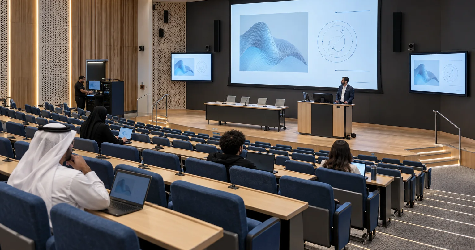
Concept visualisation of a multi-purpose hall with a stage and presentation screen
Solution 02 / 10

AV systems integration · Dubai & the UAE

Multi-purpose halls

One hall. A clear plan for every event.

Move between presentations, hybrid discussions and stage programmes.

  • Consultation
  • Design
  • Integration
  • Support
From the brief
to a working system
See how
it works
  • Different programmes

    Separate presentation, hybrid and stage modes.

  • Sound for the room

    Plan coverage around seats and activities.

  • Hybrid participation

    Define camera, content and return paths.

  • Clear changeovers

    Agree how staff move between modes.

01 · Choose a starting point

What does your team need to do?

Typical configurations, not fixed packages or completed projects. Each needs validation against your users, sources, operating conditions and site.

02 · Your selected option · MH-01

Presentation hall

A presenter connects a laptop, uses a lectern or wireless microphone and shows material on the main display.

Change option ↑

Reference design; room tests required. Read the full design notes →

How it works · functional groups

A presentation and speech in the hall

Picture

Guest laptop

Agreed HDMI format and unprotected content.

Presentation interface

Extracts stereo sound from the picture feed.

Main display

Image size follows the room and viewing positions.

Room sound

Speech + playback

Two wireless channels, lectern microphone and laptop audio.

Mixer + room processing

Channel mutes on the mixer; overall level on the room panel.

Audience

Two powered mains as the initial layout.

This option has no cameras, recording, remote call or stage monitor mixes. Speaker coverage and hearing assistance need room-specific agreement.

Devices & connections Inspect here
What these groups contain Devices and connection references

Rows explain related paths. A group can include parallel outputs; the full drawing shows individual devices, directions and conditions. Repeated IDs refer to the same equipment.

Picture

Guest laptop

LAP · 1 customer laptop

Presentation interface

EX · 1 HDMI interface · stereo extraction

Main display

MAIN · 1 main display system

Connections: L01, L02.

Room sound

Speech + playback

RF · 2 wireless channels

WIRED · 1 lectern microphone

EX · 1 HDMI interface · stereo extraction

Mixer + room processing

MIX · 1 digital mixer · 5 input channels used

PA · 1 room DSP · 2 inputs / 2 outputs used

Audience

SP · 2 powered mains · amplification included

Connections: L03, L04, L05, L06, L07.

Other devices, controls and supporting services

  • CTRL · 1 integrated panel/controller
  • NET · 1 managed switch · 4 ports planned
  • INSTALL · 1 cable set + 1 rack/power set · 1 programming work package · site quantities required
  • NOTE · Reference design; no recording or call. · Solid = media; dashed = control/status. · Local power supplies; no PoE assumed.

MH-01 · Presentation hall

Functional reference design: HDMI presentation to one main display, three microphone channels to room sound, and separate room controls.

Signal flow

Signal flow. Devices, connections and conditions follow the drawing.Open SVG ↗
MH-01 · Signal flowReference design with one presentation source, three microphones, one display and local room sound. Dashed links are commands or status. 1 cable set + 1 rack/power set 1 programming work package site quantities required Reference design; no recording or call. Solid = media; dashed = control/status. Local power supplies; no PoE assumed. Repeated device identifiers refer to the same equipment across views. Equipment illustrations are schematic; labels define quantities.{"sourceHash":"784bd461530f5f9c26aa18e22a05a242c3713555b70d1f431e42858fc56387c7","view":"signal","nodes":["LAP","EX","MAIN","RF","MIX","WIRED","PA","SP"],"edges":["L01","L02","L03","L04","L05","L06","L07"]}PIXEL COMMAND SOLUTIONS / MH-01 / SIGNAL FLOWSignal flowREFERENCE DESIGN · PROJECT VALIDATION REQUIREDLAP → EX: HDMIHDMIEX → MAIN: HDMIHDMIRF → MIX: 2 balanced analogue2 balanced analogueWIRED → MIX: 1 balanced analogue1 balanced analogueMIX → PA: ST L/R analogueST L/R analoguePA → SP: 2 line outputs2 line outputsEX → MIX: stereo line: 2 channelsstereo line: 2 channels1 customer laptopLAP1 customer laptop1 HDMI interface stereo extractionEX1 HDMI interface1 main display systemMAIN1 main display system2 wireless channelsRF2 wireless channels1 digital mixer 5 input channels usedMIX1 digital mixer1 lectern microphoneWIRED1 lectern microphone1 room DSP 2 inputs / 2 outputs usedPA1 room DSP2 powered mains amplification includedSP2 powered mainsVideo / LED dataAudio
Devices, connections & design conditions 7 connections
  • Functional reference design: HDMI presentation to one main display, three microphone channels to room sound, and separate room controls.
LAP
1 customer laptop
EX
1 HDMI interface stereo extraction
MAIN
1 main display system
RF
2 wireless channels
MIX
1 digital mixer 5 input channels used
WIRED
1 lectern microphone
PA
1 room DSP 2 inputs / 2 outputs used
SP
2 powered mains amplification included
  1. LAP → EXHDMI
  2. EX → MAINHDMI
  3. RF → MIX2 balanced analogue
  4. WIRED → MIX1 balanced analogue
  5. MIX → PAST L/R analogue
  6. PA → SP2 line outputs
  7. EX → MIXstereo line: 2 channels

1 cable set + 1 rack/power set 1 programming work package site quantities required

Reference design; no recording or call. Solid = media; dashed = control/status. Local power supplies; no PoE assumed.

Control & status

Signal flow. Devices, connections and conditions follow the drawing.Open SVG ↗
MH-01 · Control & statusReference design with one presentation source, three microphones, one display and local room sound. Dashed links are commands or status. 1 cable set + 1 rack/power set 1 programming work package site quantities required Reference design; no recording or call. Solid = media; dashed = control/status. Local power supplies; no PoE assumed. Repeated device identifiers refer to the same equipment across views. Equipment illustrations are schematic; labels define quantities.{"sourceHash":"784bd461530f5f9c26aa18e22a05a242c3713555b70d1f431e42858fc56387c7","view":"control","nodes":["MAIN","PA","CTRL","NET"],"edges":["L08","L09","L10"]}PIXEL COMMAND SOLUTIONS / MH-01 / CONTROL & STATUSControl & statusREFERENCE DESIGN · PROJECT VALIDATION REQUIREDCTRL ↔ NET: commands / status via LANcommands / status viaLANNET ↔ PA: IP commands / statusIP commands / statusNET ↔ MAIN: IP commands / statusIP commands / status1 main display systemMAIN1 main display system1 room DSP 2 inputs / 2 outputs usedPA1 room DSP1 integrated panel/controllerCTRL1 integratedpanel/controller1 managed switch 4 ports plannedNET1 managed switchControl / status
Devices, connections & design conditions 3 connections
  • Functional reference design: HDMI presentation to one main display, three microphone channels to room sound, and separate room controls.
MAIN
1 main display system
PA
1 room DSP 2 inputs / 2 outputs used
CTRL
1 integrated panel/controller
NET
1 managed switch 4 ports planned
  1. CTRL ↔ NETcommands / status via LAN
  2. NET ↔ PAIP commands / status
  3. NET ↔ MAINIP commands / status

1 cable set + 1 rack/power set 1 programming work package site quantities required

Reference design; no recording or call. Solid = media; dashed = control/status. Local power supplies; no PoE assumed.

Typical architecture · not a project drawing

03 · Scope & limits

What is included. What needs agreement.

System composition

One customer presentation device, one HDMI interface with stereo audio extraction, one main display system, two wireless microphone channels, one lectern microphone, one digital mixer and one room audio processor. Two powered main loudspeakers form the initial coverage layout. One integrated control panel/controller and the hall infrastructure complete the example.

Equipment schedule · 7 groups

Example quantities, not an approved procurement schedule. Catalogue links provide component specifications; they do not confirm system compatibility or availability.

Main / confidence / multiview displays
1 / 0 / 0

LED options; other display types by specification

LED options →
Wireless channels / wired microphone or DI channels
2 / 1

Microphones and wireless microphone systems

Microphones and wireless microphone systems →
Digital console / stage I/O unit
1 / 0

Audio processing

Audio processing →
Room audio processor / conferencing audio processor
1 / 0

Audio processing

Audio processing →
Powered main positions or groups / fills / monitors
2 / 0 / 0

Loudspeakers

Loudspeakers →
HDMI interfaces with extraction / additional HDMI splitters
1 / 0

Interfaces selected to the signal schedule

Integrated room panel/controller / stage-lighting package
1 / optional

Lighting control · Stage lighting

Lighting control →Stage lighting →
Browse equipment specifications →

What we need to demonstrate

For every hall, review real presentation material from the agreed seats, check speech coverage and microphone handover, and test startup, mute and shutdown. Record the agreed criteria and measured results. MH-02 adds a full-duration event rehearsal, each camera and presentation input, the separate room and recording mixes, lip sync, a playable exported file and destination stream checks. Loss of internet must be tested alongside local recording behaviour. MH-03 adds two-way speech with all six conference microphones, simultaneous local and remote speech, remote video excluded from the outgoing feed, and independent main/confidence views. Rehearse presentation → conference → stage → conference, including microphone state, four monitor mixes, lighting cues, recording continuity and recovery after a controlled restart. These are checks to perform on the selected system. No reference configuration in this package has passed physical acceptance testing..

Handover evidence: Agreed criteria, equipment and version schedule, measured test results and recovery procedure..

These are planned project checks. The reference configuration has not passed physical system acceptance.

Discuss this option · MH-01
02 · Your selected option · MH-02

Recorded and streamed events

An event operator switches between two camera views and presentation material, while the room audience watches the selected source and online viewers receive the programme.

Change option ↑

Reference design; recording and stream tests required. Read the full design notes →

How it works · functional groups

Operate a programme for the room and online viewers

Pictures and recording

Cameras + presentation

Two camera views and a converted HDMI source.

Production switcher

Programme to recorder; selected input or programme to the room.

Room + online viewers

Main display, programme recording and one-way stream.

Separate sound mixes

Stage inputs

Six microphone/DI channels plus stereo content.

Mixer

Separate room, monitor and recorder mixes.

Sound destinations

Processed room PA, two monitors and recorder.

A one-way stream cannot host a remote speaker. The base recorder keeps the selected programme, not separate camera files. The operator monitors sources and actual recording state.

Devices & connections Inspect here
What these groups contain Devices and connection references

Rows explain related paths. A group can include parallel outputs; the full drawing shows individual devices, directions and conditions. Repeated IDs refer to the same equipment.

Pictures and recording

Cameras + presentation

CAM · 2 PTZ cameras · local DC power

LAP · 1 customer laptop

EX · 1 HDMI interface · stereo extraction

H2S · 1 HDMI-to-SDI converter

Production switcher

SW · 1 production switcher · 3 of 8 inputs used

Room + online viewers

S2H1 · SDI-to-HDMI 1 of 2

MAIN · 1 main display system

REC · 1 recorder/encoder · 1 recording medium

DEST · Customer streaming destination · and archive workflow

Connections: L01, L02, L03, L04, L05, L06, L07, L10.

Separate sound mixes

Stage inputs

RF · 4 wireless channels

WIRED · 2 wired microphone / DI channels

EX · 1 HDMI interface · stereo extraction

SB · 1 stagebox · 8 of 16 inputs used

Mixer

MIX · 1 digital mixer · 8 of 16 inputs used

Sound destinations

PA · 1 room DSP · 2 in / 4 out used

SP · 2 powered mains

FILL · 2 powered front fills

MON · 2 powered monitors

REC · 1 recorder/encoder · 1 recording medium

Connections: L11, L12, L13, L14, L15, L16, L17, L18, L19.

Other devices, controls and supporting services

  • S2H2 · SDI-to-HDMI 2 of 2
  • MV · 1 operator multiview monitor
  • CTRL · 1 integrated panel/controller
  • NET · 1 managed AV switch · 13 ports planned · Dante / control / stream
  • OPS · 1 operator workstation · UI monitor and headphones
  • NOTE · Reference design: one-way streaming, no call return. · 2 SDI-to-HDMI converters in total; OUT 4 unused. · Room and recorder embedded audio muted. · Shared cabling, rack/power and programming counted once.

MH-02 · Recorded and streamed events

Functional reference design: two SDI cameras and presentation to production switching, room display and recording; separate room, stage monitor and record mixes.

Video & data

Signal flow. Devices, connections and conditions follow the drawing.Open SVG ↗
MH-02 · Video & dataTwo cameras and presentation feed production switching, the room display and recording. Room sound, two stage monitors and the recorder have separate mixes. Control routes use a shared switch. Reference design: one-way streaming, no call return. 2 SDI-to-HDMI converters in total; OUT 4 unused. Room and recorder embedded audio muted. Shared cabling, rack/power and programming counted once. Repeated device identifiers refer to the same equipment across views. Equipment illustrations are schematic; labels define quantities.{"sourceHash":"21dddbba9c43ea7cbfcc8d38f4dbaa3389321aa891865156f3d13c84f94151a1","view":"signal","nodes":["CAM","SW","LAP","EX","H2S","REC","S2H1","MAIN","S2H2","MV","DEST"],"edges":["L01","L02","L03","L04","L05","L06","L07","L08","L09","L10"]}PIXEL COMMAND SOLUTIONS / MH-02 / VIDEO & DATAVideo & dataREFERENCE DESIGN · PROJECT VALIDATION REQUIREDCAM → SW: 2 x 3G-SDI2 × 3G-SDILAP → EX: HDMIHDMIEX → H2S: HDMIHDMIH2S → SW: SDI input 3SDI · input 3SW → REC: OUT 1: programme SDIOUT 1 ·programmeSW → S2H1: OUT 2: AUX selected input or programmeOUT 2 · AUX selectionS2H1 → MAIN: HDMIHDMISW → S2H2: OUT 3: multiview SDIOUT 3 · multiviewS2H2 → MV: HDMIHDMIREC → DEST: encoded IP via AV switch / WANEncoded IPvia WAN2 PTZ cameras local DC powerCAM2 PTZ cameras1 production switcher 3 of 8 inputs usedSW1 production switcher1 customer laptopLAP1 customer laptop1 HDMI interface stereo extractionEX1 HDMI interface1 HDMI-to-SDI converterH2S1 HDMI-to-SDIconverter1 recorder/encoder 1 recording mediumREC1 recorder/encoderSDI-to-HDMI 1 of 2S2H1SDI-to-HDMI 1 of 21 main display systemMAIN1 main display systemSDI-to-HDMI 2 of 2S2H2SDI-to-HDMI 2 of 21 operator multiview monitorMV1 operator multiviewmonitorCustomer streaming destination and archive workflowDESTCustomer streamingdestinationVideo / LED dataNetwork / data
Devices, connections & design conditions 10 connections
  • Functional reference design: two SDI cameras and presentation to production switching, room display and recording; separate room, stage monitor and record mixes.
CAM
2 PTZ cameras local DC power
SW
1 production switcher 3 of 8 inputs used
LAP
1 customer laptop
EX
1 HDMI interface stereo extraction
H2S
1 HDMI-to-SDI converter
REC
1 recorder/encoder 1 recording medium
S2H1
SDI-to-HDMI 1 of 2
MAIN
1 main display system
S2H2
SDI-to-HDMI 2 of 2
MV
1 operator multiview monitor
DEST
Customer streaming destination and archive workflow
  1. CAM → SW2 x 3G-SDI
  2. LAP → EXHDMI
  3. EX → H2SHDMI
  4. H2S → SWSDI input 3
  5. SW → RECOUT 1: programme SDI
  6. SW → S2H1OUT 2: AUX selected input or programme
  7. S2H1 → MAINHDMI
  8. SW → S2H2OUT 3: multiview SDI
  9. S2H2 → MVHDMI
  10. REC → DESTencoded IP via AV switch / WAN

Reference design: one-way streaming, no call return. 2 SDI-to-HDMI converters in total; OUT 4 unused. Room and recorder embedded audio muted. Shared cabling, rack/power and programming counted once.

Audio & return paths

Signal flow. Devices, connections and conditions follow the drawing.Open SVG ↗
MH-02 · Audio & return pathsTwo cameras and presentation feed production switching, the room display and recording. Room sound, two stage monitors and the recorder have separate mixes. Control routes use a shared switch. Reference design: one-way streaming, no call return. 2 SDI-to-HDMI converters in total; OUT 4 unused. Room and recorder embedded audio muted. Shared cabling, rack/power and programming counted once. Repeated device identifiers refer to the same equipment across views. Equipment illustrations are schematic; labels define quantities.{"sourceHash":"21dddbba9c43ea7cbfcc8d38f4dbaa3389321aa891865156f3d13c84f94151a1","view":"audio","nodes":["EX","REC","RF","SB","WIRED","MIX","PA","SP","FILL","MON"],"edges":["L11","L12","L13","L14","L15","L16","L17","L18","L19"]}PIXEL COMMAND SOLUTIONS / MH-02 / AUDIO & RETURN PATHSAudio & return pathsREFERENCE DESIGN · PROJECT VALIDATION REQUIREDRF → SB: 4 analogue4 analogueWIRED → SB: 2 analogue2 analogueSB → MIX: 8 Dante channels via AV switch8 Dante channels via AVswitchMIX → PA: ST L/R: 2 analogueST L/R: 2 analoguePA → SP: line 1-2line 1-2PA → FILL: line 3-4line 3-4MIX → MON: AUX 1-2: 2 mono lineAUX 1-2: 2 mono lineMIX → REC: AUX 3-4: stereo lineAUX 3-4: stereo lineEX → SB: stereo line: 2 analoguestereo line: 2 analogue1 HDMI interface stereo extractionEX1 HDMI interface1 recorder/encoder 1 recording mediumREC1 recorder/encoder4 wireless channelsRF4 wireless channels1 stagebox 8 of 16 inputs usedSB1 stagebox2 wired microphone / DI channelsWIRED2 wired microphone /DI channels1 digital mixer 8 of 16 inputs usedMIX1 digital mixer1 room DSP 2 in / 4 out usedPA1 room DSP2 powered mainsSP2 powered mains2 powered front fillsFILL2 powered front fills2 powered monitorsMON2 powered monitorsAudio
Devices, connections & design conditions 9 connections
  • Functional reference design: two SDI cameras and presentation to production switching, room display and recording; separate room, stage monitor and record mixes.
EX
1 HDMI interface stereo extraction
REC
1 recorder/encoder 1 recording medium
RF
4 wireless channels
SB
1 stagebox 8 of 16 inputs used
WIRED
2 wired microphone / DI channels
MIX
1 digital mixer 8 of 16 inputs used
PA
1 room DSP 2 in / 4 out used
SP
2 powered mains
FILL
2 powered front fills
MON
2 powered monitors
  1. RF → SB4 analogue
  2. WIRED → SB2 analogue
  3. SB → MIX8 Dante channels via AV switch
  4. MIX → PAST L/R: 2 analogue
  5. PA → SPline 1-2
  6. PA → FILLline 3-4
  7. MIX → MONAUX 1-2: 2 mono line
  8. MIX → RECAUX 3-4: stereo line
  9. EX → SBstereo line: 2 analogue

Reference design: one-way streaming, no call return. 2 SDI-to-HDMI converters in total; OUT 4 unused. Room and recorder embedded audio muted. Shared cabling, rack/power and programming counted once.

Control & status

Signal flow. Devices, connections and conditions follow the drawing.Open SVG ↗
MH-02 · Control & statusTwo cameras and presentation feed production switching, the room display and recording. Room sound, two stage monitors and the recorder have separate mixes. Control routes use a shared switch. Reference design: one-way streaming, no call return. 2 SDI-to-HDMI converters in total; OUT 4 unused. Room and recorder embedded audio muted. Shared cabling, rack/power and programming counted once. Repeated device identifiers refer to the same equipment across views. Equipment illustrations are schematic; labels define quantities.{"sourceHash":"21dddbba9c43ea7cbfcc8d38f4dbaa3389321aa891865156f3d13c84f94151a1","view":"control","nodes":["CAM","SW","REC","MAIN","PA","CTRL","NET","OPS"],"edges":["L20","L21","L22","L23","L24","L25","L26"]}PIXEL COMMAND SOLUTIONS / MH-02 / CONTROL & STATUSControl & statusREFERENCE DESIGN · PROJECT VALIDATION REQUIREDCTRL ↔ NET: IPIPOPS ↔ NET: IP control and monitoringIP control andmonitoringNET ↔ CAM: IP presets / feedbackIP presets / feedbackNET ↔ SW: IP routes / statusIP routes / statusNET ↔ REC: IP record / stateIP record / stateNET ↔ PA: IP room level / statusIP room level / statusNET ↔ MAIN: IP power / input / statusIP power / input /status2 PTZ cameras local DC powerCAM2 PTZ cameras1 production switcher 3 of 8 inputs usedSW1 production switcher1 recorder/encoder 1 recording mediumREC1 recorder/encoder1 main display systemMAIN1 main display system1 room DSP 2 in / 4 out usedPA1 room DSP1 integrated panel/controllerCTRL1 integratedpanel/controller1 managed AV switch 13 ports planned Dante / control / streamNET1 managed AV switch1 operator workstation UI monitor and headphonesOPS1 operator workstationControl / status
Devices, connections & design conditions 7 connections
  • Functional reference design: two SDI cameras and presentation to production switching, room display and recording; separate room, stage monitor and record mixes.
CAM
2 PTZ cameras local DC power
SW
1 production switcher 3 of 8 inputs used
REC
1 recorder/encoder 1 recording medium
MAIN
1 main display system
PA
1 room DSP 2 in / 4 out used
CTRL
1 integrated panel/controller
NET
1 managed AV switch 13 ports planned Dante / control / stream
OPS
1 operator workstation UI monitor and headphones
  1. CTRL ↔ NETIP
  2. OPS ↔ NETIP control and monitoring
  3. NET ↔ CAMIP presets / feedback
  4. NET ↔ SWIP routes / status
  5. NET ↔ RECIP record / state
  6. NET ↔ PAIP room level / status
  7. NET ↔ MAINIP power / input / status

Reference design: one-way streaming, no call return. 2 SDI-to-HDMI converters in total; OUT 4 unused. Room and recorder embedded audio muted. Shared cabling, rack/power and programming counted once.

Typical architecture · not a project drawing

03 · Scope & limits

What is included. What needs agreement.

System composition

Four wireless and two wired microphone/DI channels, a stereo presentation feed, one digital mixer, one stage I/O unit and one room audio processor. The initial sound layout has two powered mains, two powered front fills and two powered stage monitors. Two PTZ cameras feed one HD SDI production switcher. One HDMI-to-SDI converter brings in the presentation; two SDI-to-HDMI converters serve the main display and operator multiview. A recorder/encoder with recording media receives the selected programme and a dedicated stereo audio mix. A control panel/controller, operator workstation and shared hall infrastructure support operation.

Equipment schedule · 12 groups

Example quantities, not an approved procurement schedule. Catalogue links provide component specifications; they do not confirm system compatibility or availability.

Main / confidence / multiview displays
1 / 0 / 1

LED options; other display types by specification

LED options →
Wireless channels / wired microphone or DI channels
4 / 2

Microphones and wireless microphone systems

Microphones and wireless microphone systems →
Digital console / stage I/O unit
1 / 1

Audio processing

Audio processing →
Room audio processor / conferencing audio processor
1 / 0

Audio processing

Audio processing →
Powered main positions or groups / fills / monitors
2 / 2 / 2

Loudspeakers

Loudspeakers →
PTZ cameras / USB video capture
2 / 0

Conference equipment; capture by specification

Conference equipment →
Production switcher / display matrix
1 / 0

Switchers · Matrices

Switchers →Matrices →
HDMI interfaces with extraction / additional HDMI splitters
1 / 0

Interfaces selected to the signal schedule

HDMI-to-SDI / SDI-to-HDMI converters
1 / 2

Interfaces selected to the signal schedule

Recorder / recording medium
1 / 1

Selected to format, duration and publication workflow

Conferencing PC / operator workstation
0 / 1

Selected with IT; operator workstation includes its own UI monitor

Integrated room panel/controller / stage-lighting package
1 / optional

Lighting control · Stage lighting

Lighting control →Stage lighting →
Browse equipment specifications →

What we need to demonstrate

For every hall, review real presentation material from the agreed seats, check speech coverage and microphone handover, and test startup, mute and shutdown. Record the agreed criteria and measured results. MH-02 adds a full-duration event rehearsal, each camera and presentation input, the separate room and recording mixes, lip sync, a playable exported file and destination stream checks. Loss of internet must be tested alongside local recording behaviour. MH-03 adds two-way speech with all six conference microphones, simultaneous local and remote speech, remote video excluded from the outgoing feed, and independent main/confidence views. Rehearse presentation → conference → stage → conference, including microphone state, four monitor mixes, lighting cues, recording continuity and recovery after a controlled restart. These are checks to perform on the selected system. No reference configuration in this package has passed physical acceptance testing..

Handover evidence: Agreed criteria, equipment and version schedule, measured test results and recovery procedure..

These are planned project checks. The reference configuration has not passed physical system acceptance.

Discuss this option · MH-02

02 · Your selected option · MH-03

Conference and stage modes

The technical operator prepares a presentation, a hybrid panel discussion or a rehearsed stage programme, then changes routes and controls using an approved mode table.

Change option ↑

Reference design; platform, routing and mode tests required. Read the full design notes →

How it works · functional groups

Conference sound · three distinct mixes

Call send

Six speech feeds

Individual raw microphone feeds leave the console. Content is separate.

Six-channel AEC

Echo-cancelled speech + direct content; remote audio excluded.

Conference PC

USB microphone send into the call.

Room and reference

Remote return

USB return enters the AEC device, then the console.

Console room mix

Remote + content to PA; post-fader copy back to AEC reference.

Room speakers

Processed mains and front fills.

Conference recording

Clean speech returns

Six AEC-clean feeds return only for recording.

Recording mix

Clean speech + content + remote. Raw speech excluded.

Recorder

Dedicated stereo output, separate from PA and call.

AEC reference is MIX → AEC (L07), post-fader remote + content matching actual PA playback. L11 clean returns never feed PA or AEC mic inputs. Stage mode disconnects the call; eight stage inputs and four monitors are muted in the conference baseline.

Devices & connections Inspect here
What these groups contain Devices and connection references

Rows explain related paths. A group can include parallel outputs; the full drawing shows individual devices, directions and conditions. Repeated IDs refer to the same equipment.

Call send

Six speech feeds

RF · 6 wireless speech channels

SB · 1 stagebox · 16 analogue inputs used

MIX · 1 console: at least 32 inputs · 24 processing channels used · ST stereo + 8 mono-equivalent AUX

EX · 1 HDMI interface · same device as video drawing

Six-channel AEC

AEC · 1 AEC DSP: 6 speech AEC · Dante licence at least 16x16 · RX 10 / TX 8 used · reference L/R summed to mono

Conference PC

UC · 1 conference PC · same device as video drawing

Connections: L01, L04, L05, L06, L08.

Room and reference

Remote return

UC · 1 conference PC · same device as video drawing

AEC · 1 AEC DSP: 6 speech AEC · Dante licence at least 16x16 · RX 10 / TX 8 used · reference L/R summed to mono

Console room mix

MIX · 1 console: at least 32 inputs · 24 processing channels used · ST stereo + 8 mono-equivalent AUX

Room speakers

PA · 1 room DSP · 2 in / 4 out used

SP · 2 powered main groups · cabinet count by coverage design

FILL · 2 powered front fills

Connections: L09, L10, L07, L12, L13, L14.

Conference recording

Clean speech returns

AEC · 1 AEC DSP: 6 speech AEC · Dante licence at least 16x16 · RX 10 / TX 8 used · reference L/R summed to mono

Recording mix

MIX · 1 console: at least 32 inputs · 24 processing channels used · ST stereo + 8 mono-equivalent AUX

Recorder

REC · 1 recorder/encoder · same device as video drawing

Connections: L11, L16.

Other devices, controls and supporting services

  • WIRED · 8 wired microphone / DI channels · stage mode only
  • MON · 4 powered monitors · muted in conference baseline
  • CTRL · 1 integrated panel/controller · same device as video drawing
  • NET · 1 managed AV switch · same device as video drawing · Dante / control / WAN
  • NOTE · Reference design; 48 kHz audio. · Stage mode disconnects call; conference mutes stage inputs. · AEC-clean returns never feed PA or AEC microphone inputs. · Raw speech never joins clean speech in conference recording. · Six microphone inputs use individual pre-processing direct outs.

MH-03 · Conference and stage modes

Functional reference design: six individual conference microphone feeds, echo reference, separate USB call send and return, room sound, four monitor mixes and recording.

Audio & return paths

Signal flow. Devices, connections and conditions follow the drawing.Open SVG ↗
MH-03-audio · Audio & return pathsSix independent speech AEC channels receive an external reference. Remote return enters room and recording mixes, never the call send. Eight stage inputs and four monitors belong to the separate stage mode. Reference design; 48 kHz audio. Stage mode disconnects call; conference mutes stage inputs. AEC-clean returns never feed PA or AEC microphone inputs. Raw speech never joins clean speech in conference recording. Six microphone inputs use individual pre-processing direct outs. Repeated device identifiers refer to the same equipment across views. Equipment illustrations are schematic; labels define quantities.{"sourceHash":"1aa3f3caaf87e3d22e99510f44ef044e54dc10bff8a7a86e4a6887ad8a68f077","view":"audio","nodes":["RF","SB","WIRED","EX","MIX","AEC","UC","PA","SP","FILL","MON","REC"],"edges":["L01","L02","L03","L04","L05","L06","L07","L08","L09","L10","L11","L12","L13","L14","L15","L16"]}PIXEL COMMAND SOLUTIONS / MH-03-audio / AUDIO & RETURN PATHSAudio & return pathsREFERENCE DESIGN · PROJECT VALIDATION REQUIREDRF → SB: 6 analogue6 speech channelsWIRED → SB: 8 analogue8 stagechannelsEX → SB: stereo line: 2 analogueStereo contentSB → MIX: 16 Dante via AV switch16 DantechannelsMIX → AEC: Dante 1-6: individual raw speech1–6 · raw speechMIX → AEC: Dante 7-8: direct content L/R7–8 · content L/RMIX → AEC: Dante 9-10: reference AUX7-8 post-fader remote + content only same dual-mono PA content9–10 · AEC referenceAEC → UC: USB send: AEC speech + content remote excludedUSB send · noremoteUC → AEC: USB receive: remote L/RUSB receive · remoteAEC → MIX: Dante TX1-2: remote L/RTX1–2 · remote L/RAEC → MIX: Dante TX3-8: AEC-clean speech6 record-only returnsTX3–8 · clean speechMIX → PA: ST L/R: 2 line outputsST L/R · room mixPA → SP: line 1-2Line 1–2PA → FILL: line 3-4Line 3–4MIX → MON: AUX1-4: 4 mono line outputsAUX1–4 · stage onlyMIX → REC: AUX5-6: stereo line conference: clean speech + content + remote stage: raw sources + contentAUX5–6 · recording6 wireless speech channelsRF6 wireless speechchannels1 stagebox 16 analogue inputs usedSB1 stagebox8 wired microphone / DI channels stage mode onlyWIRED8 wired microphone /DI channels1 HDMI interface same device as video drawingEX1 HDMI interface1 console: at least 32 inputs 24 processing channels used ST stereo + 8 mono-equivalent AUXMIX1 console: at least 32inputs1 AEC DSP: 6 speech AEC Dante licence at least 16x16 RX 10 / TX 8 used reference L/R summed to monoAEC1 AEC DSP: 6 speechAEC1 conference PC same device as video drawingUC1 conference PC1 room DSP 2 in / 4 out usedPA1 room DSP2 powered main groups cabinet count by coverage designSP2 powered main groups2 powered front fillsFILL2 powered front fills4 powered monitors muted in conference baselineMON4 powered monitors1 recorder/encoder same device as video drawingREC1 recorder/encoderAudioUSB / KVM
Devices, connections & design conditions 16 connections
  • Functional reference design: six individual conference microphone feeds, echo reference, separate USB call send and return, room sound, four monitor mixes and recording.
RF
6 wireless speech channels
SB
1 stagebox 16 analogue inputs used
WIRED
8 wired microphone / DI channels stage mode only
EX
1 HDMI interface same device as video drawing
MIX
1 console: at least 32 inputs 24 processing channels used ST stereo + 8 mono-equivalent AUX
AEC
1 AEC DSP: 6 speech AEC Dante licence at least 16x16 RX 10 / TX 8 used reference L/R summed to mono
UC
1 conference PC same device as video drawing
PA
1 room DSP 2 in / 4 out used
SP
2 powered main groups cabinet count by coverage design
FILL
2 powered front fills
MON
4 powered monitors muted in conference baseline
REC
1 recorder/encoder same device as video drawing
  1. RF → SB6 analogue
  2. WIRED → SB8 analogue
  3. EX → SBstereo line: 2 analogue
  4. SB → MIX16 Dante via AV switch
  5. MIX → AECDante 1-6: individual raw speech
  6. MIX → AECDante 7-8: direct content L/R
  7. MIX → AECDante 9-10: reference AUX7-8 post-fader remote + content only same dual-mono PA content
  8. AEC → UCUSB send: AEC speech + content remote excluded
  9. UC → AECUSB receive: remote L/R
  10. AEC → MIXDante TX1-2: remote L/R
  11. AEC → MIXDante TX3-8: AEC-clean speech6 record-only returns
  12. MIX → PAST L/R: 2 line outputs
  13. PA → SPline 1-2
  14. PA → FILLline 3-4
  15. MIX → MONAUX1-4: 4 mono line outputs
  16. MIX → RECAUX5-6: stereo line conference: clean speech + content + remote stage: raw sources + content

Reference design; 48 kHz audio. Stage mode disconnects call; conference mutes stage inputs. AEC-clean returns never feed PA or AEC microphone inputs. Raw speech never joins clean speech in conference recording. Six microphone inputs use individual pre-processing direct outs.

Control & status

Signal flow. Devices, connections and conditions follow the drawing.Open SVG ↗
MH-03-audio · Control & statusSix independent speech AEC channels receive an external reference. Remote return enters room and recording mixes, never the call send. Eight stage inputs and four monitors belong to the separate stage mode. Reference design; 48 kHz audio. Stage mode disconnects call; conference mutes stage inputs. AEC-clean returns never feed PA or AEC microphone inputs. Raw speech never joins clean speech in conference recording. Six microphone inputs use individual pre-processing direct outs. Repeated device identifiers refer to the same equipment across views. Equipment illustrations are schematic; labels define quantities.{"sourceHash":"1aa3f3caaf87e3d22e99510f44ef044e54dc10bff8a7a86e4a6887ad8a68f077","view":"control","nodes":["MIX","AEC","PA","CTRL","NET"],"edges":["L17","L18","L19","L20"]}PIXEL COMMAND SOLUTIONS / MH-03-audio / CONTROL & STATUSControl & statusREFERENCE DESIGN · PROJECT VALIDATION REQUIREDCTRL ↔ NET: IP commands / stateIP commands / stateNET ↔ AEC: IP preset / statusIP preset / statusNET ↔ MIX: IP mode / statusIP mode / statusNET ↔ PA: IP calibration / statusIP calibration / status1 console: at least 32 inputs 24 processing channels used ST stereo + 8 mono-equivalent AUXMIX1 console: at least 32inputs1 AEC DSP: 6 speech AEC Dante licence at least 16x16 RX 10 / TX 8 used reference L/R summed to monoAEC1 AEC DSP: 6 speechAEC1 room DSP 2 in / 4 out usedPA1 room DSP1 integrated panel/controller same device as video drawingCTRL1 integratedpanel/controller1 managed AV switch same device as video drawing Dante / control / WANNET1 managed AV switchControl / status
Devices, connections & design conditions 4 connections
  • Functional reference design: six individual conference microphone feeds, echo reference, separate USB call send and return, room sound, four monitor mixes and recording.
MIX
1 console: at least 32 inputs 24 processing channels used ST stereo + 8 mono-equivalent AUX
AEC
1 AEC DSP: 6 speech AEC Dante licence at least 16x16 RX 10 / TX 8 used reference L/R summed to mono
PA
1 room DSP 2 in / 4 out used
CTRL
1 integrated panel/controller same device as video drawing
NET
1 managed AV switch same device as video drawing Dante / control / WAN
  1. CTRL ↔ NETIP commands / state
  2. NET ↔ AECIP preset / status
  3. NET ↔ MIXIP mode / status
  4. NET ↔ PAIP calibration / status

Reference design; 48 kHz audio. Stage mode disconnects call; conference mutes stage inputs. AEC-clean returns never feed PA or AEC microphone inputs. Raw speech never joins clean speech in conference recording. Six microphone inputs use individual pre-processing direct outs.

Typical architecture · not a project drawing

How it works · functional groups

Local programme, remote return and stage cues

Outgoing call picture

Local sources

Three PTZ cameras and presentation content.

Production + capture

Select the local programme for USB video capture.

Remote participants

Conference PC sends this local programme.

Room and recording

Local + remote pictures

Local programme, direct slides and the separate call return.

Independent destinations

Display matrix and recorder have their own inputs.

Room views

Main and confidence displays; recorder can combine local and remote.

Remote video never enters the production switcher, so it cannot return to the call. The operator confirms presentation, conference or stage mode; stage lighting follows an agreed cue plan.

Devices & connections Inspect here
What these groups contain Devices and connection references

Rows explain related paths. A group can include parallel outputs; the full drawing shows individual devices, directions and conditions. Repeated IDs refer to the same equipment.

Outgoing call picture

Local sources

CAM · 3 PTZ cameras · local DC power

LAP · 1 customer laptop

EX · 1 HDMI interface · 2 mirrored outs + stereo extraction

H2S · 1 HDMI-to-SDI converter

Production + capture

SW · 1 production switcher · 4 of 8 inputs used

CAP · 1 SDI-to-USB capture · video only in call

Remote participants

UC · 1 conference PC · own UI monitor + HDMI remote out

REMOTE · Remote participants

Connections: L01, L02, L03, L04, L05, L06, L19.

Room and recording

Local + remote pictures

SW · 1 production switcher · 4 of 8 inputs used

EX · 1 HDMI interface · 2 mirrored outs + stereo extraction

UC · 1 conference PC · own UI monitor + HDMI remote out

SPLIT · 1 HDMI 1x2 splitter

Independent destinations

S2H1 · SDI-to-HDMI 1 of 2

MATRIX · 1 HDMI matrix · at least 3 in / 2 independent out

REC · 1 recorder/encoder · 1 recording medium · local + remote layout

Room views

MAIN · 1 main display system

CONF · 1 confidence display

REC · 1 recorder/encoder · 1 recording medium · local + remote layout

Connections: L07, L08, L09, L10, L11, L12, L13, L14, L15.

Other devices, controls and supporting services

  • S2H2 · SDI-to-HDMI 2 of 2
  • MV · 1 operator multiview monitor
  • DEST · Customer stream / archive
  • CTRL · 1 integrated panel/controller
  • NET · 1 managed AV switch · 18 ports planned
  • OPS · 1 operator workstation · UI monitor + headphones
  • LIGHT · 1 stage-lighting package · console to DMX distribution and fixtures · fixture count and power by design
  • NOTE · Reference design; HD media paths. · Remote video has no path into the production switcher. · See audio drawing for USB sound, record mix and content audio. · Duplicated device labels refer to the same equipment.

MH-03 · Conference and stage modes

Functional reference design: local programme feeds the call; remote video goes separately to displays and the recorder, avoiding a video return loop.

Signal flow

Signal flow. Devices, connections and conditions follow the drawing.Open SVG ↗
MH-03-video · Signal flowThree cameras and presentation create the local programme sent to the call. Remote video travels separately to the display matrix and recorder. The audio companion drawing contains the same recorder, PC and controller. Reference design; HD media paths. Remote video has no path into the production switcher. See audio drawing for USB sound, record mix and content audio. Duplicated device labels refer to the same equipment. Repeated device identifiers refer to the same equipment across views. Equipment illustrations are schematic; labels define quantities.{"sourceHash":"e0cc33f0a793a865c594d92a5a31e7498c10dadce4ba1bfa7c1b31307323b0df","view":"signal","nodes":["CAM","SW","LAP","EX","H2S","CAP","UC","REC","S2H1","MATRIX","SPLIT","MAIN","CONF","S2H2","MV","DEST","REMOTE"],"edges":["L01","L02","L03","L04","L05","L06","L07","L08","L09","L10","L11","L12","L13","L14","L15","L16","L17","L18","L19"]}PIXEL COMMAND SOLUTIONS / MH-03-video / SIGNAL FLOWSignal flowREFERENCE DESIGN · PROJECT VALIDATION REQUIREDCAM → SW: 3 x SDI inputs 1-3SDI ·inputs1–3LAP → EX: HDMIHDMIEX → H2S: HDMI AHDMI AH2S → SW: SDI input 4SDI · input 4SW → CAP: OUT 2: local programme SDIOUT 2 ·programmeCAP → UC: USB 3 videoUSB 3 videoSW → REC: OUT 1: local programme SDIOUT 1 · programmeSW → S2H1: OUT 3: local programme SDIOUT 3 · programmeS2H1 → MATRIX: HDMI input 2HDMI · input 2EX → MATRIX: HDMI B: slides input 1HDMI B · slidesUC → SPLIT: HDMI: remote view onlyHDMI · remote viewSPLIT → MATRIX: HDMI input 3HDMI · input 3SPLIT → REC: HDMI remote galleryRemote galleryMATRIX → MAIN: HDMI out 1HDMI · out 1MATRIX → CONF: HDMI out 2HDMI · out 2SW → S2H2: OUT 4: multiview SDIOUT 4 · multiviewS2H2 → MV: HDMIHDMIREC → DEST: encoded IP via switch / WANEncoded IPvia WANUC ↔ REMOTE: platform via switch / WANCall via WAN3 PTZ cameras local DC powerCAM3 PTZ cameras1 production switcher 4 of 8 inputs usedSW1 production switcher1 customer laptopLAP1 customer laptop1 HDMI interface 2 mirrored outs + stereo extractionEX1 HDMI interface1 HDMI-to-SDI converterH2S1 HDMI-to-SDIconverter1 SDI-to-USB capture video only in callCAP1 SDI-to-USB capture1 conference PC own UI monitor + HDMI remote outUC1 conference PC1 recorder/encoder 1 recording medium local + remote layoutREC1 recorder/encoderSDI-to-HDMI 1 of 2S2H1SDI-to-HDMI 1 of 21 HDMI matrix at least 3 in / 2 independent outMATRIX1 HDMI matrix1 HDMI 1x2 splitterSPLIT1 HDMI 1x2 splitter1 main display systemMAIN1 main display system1 confidence displayCONF1 confidence displaySDI-to-HDMI 2 of 2S2H2SDI-to-HDMI 2 of 21 operator multiview monitorMV1 operator multiviewmonitorCustomer stream / archiveDESTCustomer stream /archiveRemote participantsREMOTERemote participantsVideo / LED dataUSB / KVMNetwork / data
Devices, connections & design conditions 19 connections
  • Functional reference design: local programme feeds the call; remote video goes separately to displays and the recorder, avoiding a video return loop.
CAM
3 PTZ cameras local DC power
SW
1 production switcher 4 of 8 inputs used
LAP
1 customer laptop
EX
1 HDMI interface 2 mirrored outs + stereo extraction
H2S
1 HDMI-to-SDI converter
CAP
1 SDI-to-USB capture video only in call
UC
1 conference PC own UI monitor + HDMI remote out
REC
1 recorder/encoder 1 recording medium local + remote layout
S2H1
SDI-to-HDMI 1 of 2
MATRIX
1 HDMI matrix at least 3 in / 2 independent out
SPLIT
1 HDMI 1x2 splitter
MAIN
1 main display system
CONF
1 confidence display
S2H2
SDI-to-HDMI 2 of 2
MV
1 operator multiview monitor
DEST
Customer stream / archive
REMOTE
Remote participants
  1. CAM → SW3 x SDI inputs 1-3
  2. LAP → EXHDMI
  3. EX → H2SHDMI A
  4. H2S → SWSDI input 4
  5. SW → CAPOUT 2: local programme SDI
  6. CAP → UCUSB 3 video
  7. SW → RECOUT 1: local programme SDI
  8. SW → S2H1OUT 3: local programme SDI
  9. S2H1 → MATRIXHDMI input 2
  10. EX → MATRIXHDMI B: slides input 1
  11. UC → SPLITHDMI: remote view only
  12. SPLIT → MATRIXHDMI input 3
  13. SPLIT → RECHDMI remote gallery
  14. MATRIX → MAINHDMI out 1
  15. MATRIX → CONFHDMI out 2
  16. SW → S2H2OUT 4: multiview SDI
  17. S2H2 → MVHDMI
  18. REC → DESTencoded IP via switch / WAN
  19. UC ↔ REMOTEplatform via switch / WAN

Reference design; HD media paths. Remote video has no path into the production switcher. See audio drawing for USB sound, record mix and content audio. Duplicated device labels refer to the same equipment.

Control & status

Signal flow. Devices, connections and conditions follow the drawing.Open SVG ↗
MH-03-video · Control & statusThree cameras and presentation create the local programme sent to the call. Remote video travels separately to the display matrix and recorder. The audio companion drawing contains the same recorder, PC and controller. Reference design; HD media paths. Remote video has no path into the production switcher. See audio drawing for USB sound, record mix and content audio. Duplicated device labels refer to the same equipment. Repeated device identifiers refer to the same equipment across views. Equipment illustrations are schematic; labels define quantities.{"sourceHash":"e0cc33f0a793a865c594d92a5a31e7498c10dadce4ba1bfa7c1b31307323b0df","view":"control","nodes":["CAM","SW","REC","MATRIX","MAIN","CTRL","NET","OPS","LIGHT"],"edges":["L20","L21","L22","L23","L24","L25","L26","L27"]}PIXEL COMMAND SOLUTIONS / MH-03-video / CONTROL & STATUSControl & statusREFERENCE DESIGN · PROJECT VALIDATION REQUIREDCTRL ↔ NET: IPIPOPS ↔ NET: IP operation / monitoringIP operation /monitoringNET ↔ CAM: IP presets / feedbackIP presets / feedbackNET ↔ SW: IP routing / statusIP routing / statusNET ↔ MATRIX: IP routes / statusIP routes / statusNET ↔ REC: IP recording / actual stateIP recording /actual stateNET ↔ MAIN: IP commands / statusIP commands / statusNET ↔ LIGHT: IP cue request / statusIP cue request / status3 PTZ cameras local DC powerCAM3 PTZ cameras1 production switcher 4 of 8 inputs usedSW1 production switcher1 recorder/encoder 1 recording medium local + remote layoutREC1 recorder/encoder1 HDMI matrix at least 3 in / 2 independent outMATRIX1 HDMI matrix1 main display systemMAIN1 main display system1 integrated panel/controllerCTRL1 integratedpanel/controller1 managed AV switch 18 ports plannedNET1 managed AV switch1 operator workstation UI monitor + headphonesOPS1 operator workstation1 stage-lighting package console to DMX distribution and fixtures fixture count and power by designLIGHT1 stage-lightingpackageControl / status
Devices, connections & design conditions 8 connections
  • Functional reference design: local programme feeds the call; remote video goes separately to displays and the recorder, avoiding a video return loop.
CAM
3 PTZ cameras local DC power
SW
1 production switcher 4 of 8 inputs used
REC
1 recorder/encoder 1 recording medium local + remote layout
MATRIX
1 HDMI matrix at least 3 in / 2 independent out
MAIN
1 main display system
CTRL
1 integrated panel/controller
NET
1 managed AV switch 18 ports planned
OPS
1 operator workstation UI monitor + headphones
LIGHT
1 stage-lighting package console to DMX distribution and fixtures fixture count and power by design
  1. CTRL ↔ NETIP
  2. OPS ↔ NETIP operation / monitoring
  3. NET ↔ CAMIP presets / feedback
  4. NET ↔ SWIP routing / status
  5. NET ↔ MATRIXIP routes / status
  6. NET ↔ RECIP recording / actual state
  7. NET ↔ MAINIP commands / status
  8. NET ↔ LIGHTIP cue request / status

Reference design; HD media paths. Remote video has no path into the production switcher. See audio drawing for USB sound, record mix and content audio. Duplicated device labels refer to the same equipment.

Typical architecture · not a project drawing

Operating modes

ModeMain / confidence displaysRoom and recording soundCall and lighting
PresentationSlides / slidesPresenter and programme; recording only when authorisedCall disconnected; presentation lighting
Hybrid conferenceSelected local view or remote participants / slidesSix speech microphones, content and remote return; separate record mixSix echo-processed microphones and content sent; remote return excluded; conference lighting
Stage programmeSelected local programme / agreed sourceStage microphones/DI, programme and four monitor mixes; separate record mixCall disconnected; operator-controlled stage cues

03 · Scope & limits

What is included. What needs agreement.

System composition

Six wireless speech channels and eight wired microphone/DI channels, one stage I/O unit and a digital console with at least 32 processing inputs. An echo-cancelling processor handles six separate conference microphone feeds, USB call audio and the recording speech returns. Room sound processing feeds two powered main groups and two powered front fills as an initial layout; four powered monitors have individual mixes. Three PTZ cameras and the presentation feed a production switcher. A separate display matrix serves the main and confidence displays. One conferencing PC, one SDI-to-USB capture device, one recorder with media, two HDMI distribution interfaces, one HDMI-to-SDI converter and two SDI-to-HDMI converters complete the media paths. Controls, an operator workstation and a designed stage-lighting package support the modes.

Equipment schedule · 12 groups

Example quantities, not an approved procurement schedule. Catalogue links provide component specifications; they do not confirm system compatibility or availability.

Main / confidence / multiview displays
1 / 1 / 1

LED options; other display types by specification

LED options →
Wireless channels / wired microphone or DI channels
6 / 8

Microphones and wireless microphone systems

Microphones and wireless microphone systems →
Digital console / stage I/O unit
1 / 1

Audio processing

Audio processing →
Room audio processor / conferencing audio processor
1 / 1

Audio processing

Audio processing →
Powered main positions or groups / fills / monitors
2 groups / 2 / 4

Loudspeakers

Loudspeakers →
PTZ cameras / USB video capture
3 / 1

Conference equipment; capture by specification

Conference equipment →
Production switcher / display matrix
1 / 1

Switchers · Matrices

Switchers →Matrices →
HDMI interfaces with extraction / additional HDMI splitters
1 / 1

Interfaces selected to the signal schedule

HDMI-to-SDI / SDI-to-HDMI converters
1 / 2

Interfaces selected to the signal schedule

Recorder / recording medium
1 / 1

Selected to format, duration and publication workflow

Conferencing PC / operator workstation
1 / 1

Selected with IT; operator workstation includes its own UI monitor

Integrated room panel/controller / stage-lighting package
1 / 1

Lighting control · Stage lighting

Lighting control →Stage lighting →
Browse equipment specifications →

What we need to demonstrate

For every hall, review real presentation material from the agreed seats, check speech coverage and microphone handover, and test startup, mute and shutdown. Record the agreed criteria and measured results. MH-02 adds a full-duration event rehearsal, each camera and presentation input, the separate room and recording mixes, lip sync, a playable exported file and destination stream checks. Loss of internet must be tested alongside local recording behaviour. MH-03 adds two-way speech with all six conference microphones, simultaneous local and remote speech, remote video excluded from the outgoing feed, and independent main/confidence views. Rehearse presentation → conference → stage → conference, including microphone state, four monitor mixes, lighting cues, recording continuity and recovery after a controlled restart. These are checks to perform on the selected system. No reference configuration in this package has passed physical acceptance testing..

Handover evidence: Agreed criteria, equipment and version schedule, measured test results and recovery procedure..

These are planned project checks. The reference configuration has not passed physical system acceptance.

Discuss this option · MH-03

04 · From brief to handover

Agree the workflow before choosing the hardware.

Start with the people, activities and operating conditions. Confirm the design, interfaces and acceptance plan before procurement and installation.

  1. 01

    Scope and architecture

    Event and mode list; operator responsibilities; included subsystems and external services

  2. 02

    Design and approval

    Display and sound layouts; audio/video routing and mode tables; stage connections, network and power schedules

  3. 03

    Selection and supply

    Agreed equipment schedule; checked converters, capture and audio interfaces; software, licences and recording media

  4. 04

    Installation and programming

    Installed and labelled system; configured mixes, camera presets and room modes; device status and recovery controls

  5. 05

    Commissioning and tests

    Each agreed event mode tested; changeovers and failure recovery checked; recording, stream or call reports where included

  6. 06

    Handover

    Operator rehearsal and training; as-built schematics and saved configurations; startup, recording and fault-recovery guides

Detailed stages and deliverables →

05 · Team experience

Related work, with its own brief.

These documented projects are separate from the reference designs (MH-01, MH-02, MH-03). Each records its own scope and outcome.

Illustrative visualisation of an auditorium stage with a central screen and side displays, not the project site
Illustrative visual
RC-07
Multi-purpose halls

Multi-purpose complex, 249 seats

Conference, lecture, esports tournament and concert in one hall, switched between agreed operating modes by one control system.

Hall
249 seats and ten esports stations
Display
Central and side LED screens
Video
IP video transport, PTZ cameras (NDI, HDMI, 3G-SDI), recording and streaming

The control processor switches the complex between conference, lecture, esports tournament and concert using preset profiles.

Illustrative visualisation of a lecture auditorium with stage displays, not the project site
Illustrative visual
RC-08
Multi-purpose halls

Multi-purpose hall sound system, 1,008 seats

Sound reinforcement, simultaneous interpretation and background sound for a 1,008-seat multi-purpose hall and the teaching and rehearsal spaces around it, designed from an electroacoustic model of the hall.

Hall
1,008 seats, stage and forestage
Main system
Left and right flown line arrays of 12 elements, 4 flown subwoofers per side
Fills
8 front fills, 8 stage monitors, 2 side fills

Working documentation issued and revised after review; the model predicts direct sound above 96 dB across the seating and STI 0.58–0.66.

Explore our team’s project experience →

Planning a specification?

The full technical notes retain application scenarios, detailed architecture, design parameters, interfaces, standards, available project drawings and questions to resolve.

Design requirements →IT and building interfaces →Project drawing →Inputs and FAQ →

Next step

Share your hall brief.

Send the hall plan, seating, stage arrangement and event list. Your selected configuration will be included in the enquiry.