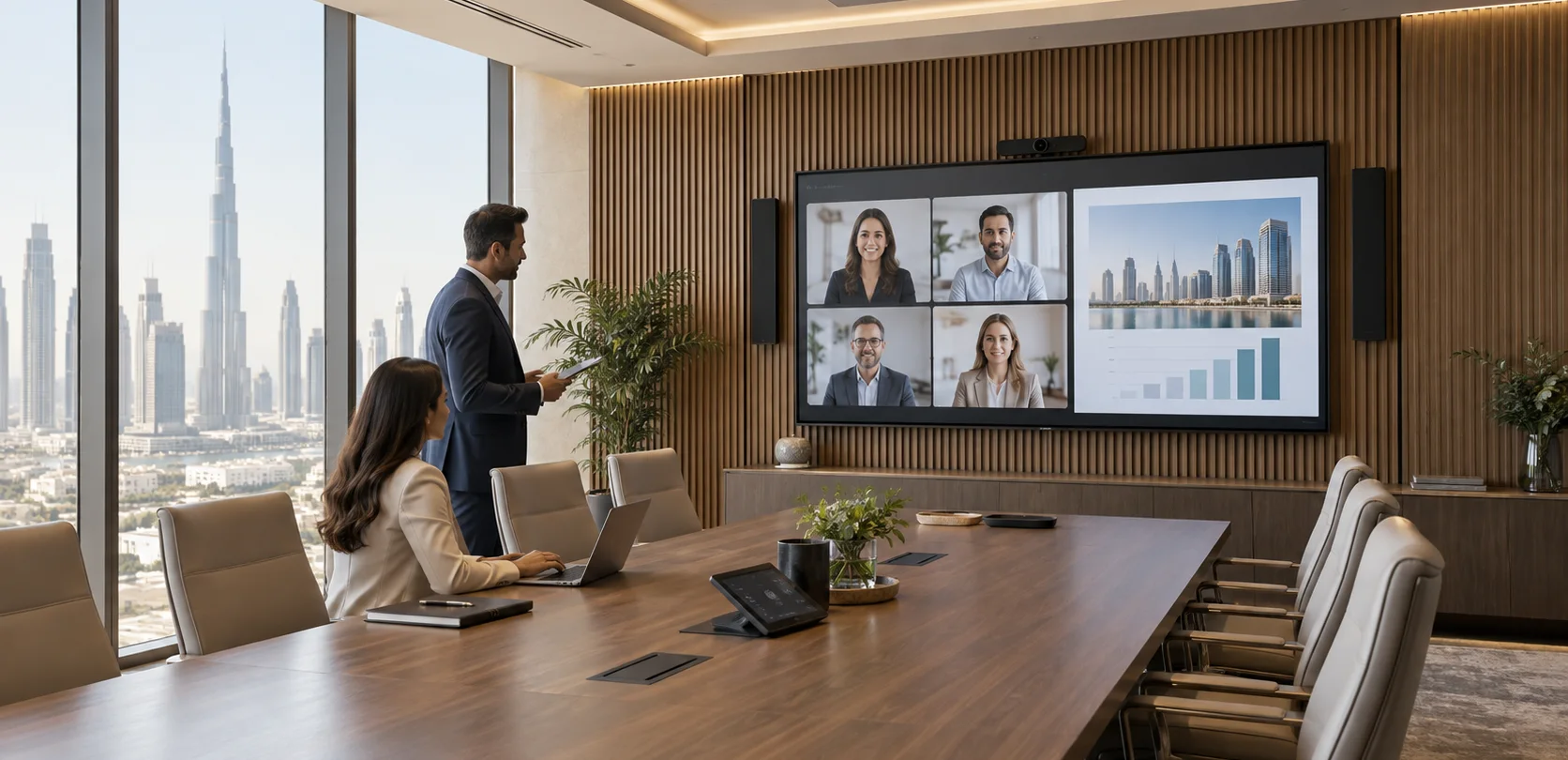
Concept visualisation of a Dubai executive boardroom with integrated hybrid meeting technology
Solution 01 / 10

AV systems integration · Dubai & the UAE

Meeting & conference rooms

Bring everyone into the conversation.

Present, meet and collaborate with people in the room and online.

  • Consultation
  • Design
  • Integration
  • Support
From the brief
to a working system
See how
it works
  • Clear presentations

    Start with content and viewing positions.

  • Connected teams

    Include people in the room and online.

  • Speech that matters

    Plan microphone coverage and echo control.

  • Everyday operation

    Agree the room controls and user workflow.

01 · Choose a starting point

What does your team need to do?

Typical configurations, not fixed packages or completed projects. Each needs validation against your users, sources, operating conditions and site.

02 · Your selected option · MR-01

Laptop-led meeting

A guest or employee uses their laptop to start a call and share material in a small room.

Change option ↑

Reference design; laptop and room tests required. Read the full design notes →

How it works · functional groups

Bring a laptop and start the meeting

Room picture

Your laptop

Runs the call and shares content; HDMI is separate from USB.

Room display

The selected material; display speakers off.

Call sound + camera

USB video bar

Camera, microphones, echo cancellation and speakers.

Laptop application

USB camera and processed speech; return sound to the bar.

Remote participants

Customer network and conferencing service.

HDMI, USB and charging are separate connections. There is no permanent room PC or managed room-platform claim in this baseline.

Devices & connections Inspect here
What these groups contain Devices and connection references

Rows explain related paths. A group can include parallel outputs; the full drawing shows individual devices, directions and conditions. Repeated IDs refer to the same equipment.

Room picture

Your laptop

PC · 1 user laptop · Call application and screen sharing

Room display

DIS · 1 display · 65-inch candidate; speakers off

Connections: L01.

Call sound + camera

USB video bar

BAR · 1 USB video bar · Camera, microphones, AEC, speakers

Laptop application

PC · 1 user laptop · Call application and screen sharing

Remote participants

REM · Remote participants · Client conferencing service

Connections: L02, L03, L04.

Other devices, controls and supporting services

  • OP · User operation · Laptop UI; local device controls
  • POWER · Room power and installation · Display and bar supplies; laptop charger
  • NOTE · No room PC or managed platform in this baseline. · HDMI and USB are separate; laptop charging is separate. · Reference design: project selection and tests required.

MR-01 · Laptop-led meeting

The laptop sends HDMI to the display and exchanges camera, microphone and playback audio with a USB video bar.

Signal flow

Signal flow. Devices, connections and conditions follow the drawing.Open SVG ↗
MR-01 · Signal flowLaptop HDMI directly to the display and USB camera, microphone and playback through one video bar. Local controls and separate power supplies. No room PC or managed platform in this baseline. HDMI and USB are separate; laptop charging is separate. Reference design: project selection and tests required. Repeated device identifiers refer to the same equipment across views. Equipment illustrations are schematic; labels define quantities.{"sourceHash":"b45d0c90a9790d1547dde74827566ab543849f32e98cf81845384945b54fd141","view":"signal","nodes":["PC","DIS","BAR","REM"],"edges":["L01","L02","L03","L04"]}PIXEL COMMAND SOLUTIONS / MR-01 / SIGNAL FLOWSignal flowREFERENCE DESIGN · PROJECT VALIDATION REQUIREDPC → DIS: HDMI: selected materialHDMI: selected materialBAR → PC: USB camera + processed microphoneUSB camera + processedmicrophonePC → BAR: USB playback; internal AEC referenceUSB playbackPC ↔ REM: IP call via client networkIP call via clientnetwork1 user laptop Call application and screen sharingPC1 user laptop1 display 65-inch candidate; speakers offDIS1 display1 USB video bar Camera, microphones, AEC, speakersBAR1 USB video barRemote participants Client conferencing serviceREMRemote participantsVideo / LED dataUSB / KVMNetwork / data
Devices, connections & design conditions 4 connections
  • The laptop sends HDMI to the display and exchanges camera, microphone and playback audio with a USB video bar.
  • MR-01 reference diagram with separate HDMI and USB paths, local controls and the laptop's network call.
PC
1 user laptop Call application and screen sharing
DIS
1 display 65-inch candidate; speakers off
BAR
1 USB video bar Camera, microphones, AEC, speakers
REM
Remote participants Client conferencing service
  1. PC → DISHDMI: selected material
  2. BAR → PCUSB camera + processed microphone
  3. PC → BARUSB playback; internal AEC reference
  4. PC ↔ REMIP call via client network

No room PC or managed platform in this baseline. HDMI and USB are separate; laptop charging is separate. Reference design: project selection and tests required.

Control & power

Signal flow. Devices, connections and conditions follow the drawing.Open SVG ↗
MR-01 · Control & powerLaptop HDMI directly to the display and USB camera, microphone and playback through one video bar. Local controls and separate power supplies. No room PC or managed platform in this baseline. HDMI and USB are separate; laptop charging is separate. Reference design: project selection and tests required. Repeated device identifiers refer to the same equipment across views. Equipment illustrations are schematic; labels define quantities.{"sourceHash":"b45d0c90a9790d1547dde74827566ab543849f32e98cf81845384945b54fd141","view":"control","nodes":["PC","DIS","BAR","OP","POWER"],"edges":["L05","L06","L07","L08","L09"]}PIXEL COMMAND SOLUTIONS / MR-01 / CONTROL & POWERControl & powerREFERENCE DESIGN · PROJECT VALIDATION REQUIREDOP → PC: Start, share, device selectionStart, share,device selectionOP → BAR: Local mute / level; verify stateLocal mute / levelOP → DIS: Power / inputPower / inputPOWER → BAR: Separate power suppliesSeparate powersuppliesPOWER → DIS: ACAC1 user laptop Call application and screen sharingPC1 user laptop1 display 65-inch candidate; speakers offDIS1 display1 USB video bar Camera, microphones, AEC, speakersBAR1 USB video barUser operation Laptop UI; local device controlsOPUser operationRoom power and installation Display and bar supplies; laptop chargerPOWERRoom power andinstallationControl / statusPower
Devices, connections & design conditions 5 connections
  • The laptop sends HDMI to the display and exchanges camera, microphone and playback audio with a USB video bar.
  • MR-01 reference diagram with separate HDMI and USB paths, local controls and the laptop's network call.
PC
1 user laptop Call application and screen sharing
DIS
1 display 65-inch candidate; speakers off
BAR
1 USB video bar Camera, microphones, AEC, speakers
OP
User operation Laptop UI; local device controls
POWER
Room power and installation Display and bar supplies; laptop charger
  1. OP → PCStart, share, device selection
  2. OP → BARLocal mute / level; verify state
  3. OP → DISPower / input
  4. POWER → BARSeparate power supplies
  5. POWER → DISAC

No room PC or managed platform in this baseline. HDMI and USB are separate; laptop charging is separate. Reference design: project selection and tests required.

Typical architecture · not a project drawing

03 · Scope & limits

What is included. What needs agreement.

System composition

One display, one USB video bar with camera, microphones, speakers and echo cancellation, and the user's laptop. Separate USB and HDMI paths connect the room devices. The installation includes mounting, power, labelled cables and agreed laptop adapters where required.

Equipment schedule · 5 groups

Example quantities, not an approved procurement schedule. Catalogue links provide component specifications; they do not confirm system compatibility or availability.

Display
1

Commercial display requirements confirmed per room

User laptop / dedicated room PC
1 user laptop

Selected with IT

Integrated USB video bar
1

Selected for the agreed laptop and room

Installation set
1

Cables, mounts, power and labels by surveyed routes

Software and entitlements
User application

Version and licence schedule

Browse equipment specifications →

What we need to demonstrate

Connect each supported laptop type, select room devices, call, share content and reconnect.

Handover evidence: Laptop/OS matrix and connection/call results.

These are planned project checks. The reference configuration has not passed physical system acceptance.

Discuss this option · MR-01
02 · Your selected option · MR-02

Dedicated room PC

A regular team starts recurring calls from a permanent PC, with a ceiling microphone and a separate camera positioned for the seating.

Change option ↑

Reference design; platform and room tests required. Read the full design notes →

How it works · functional groups

Use a permanent room PC for recurring meetings

Picture and call

PTZ camera

One camera through a dedicated capture device.

Room PC

Start the meeting and share content in the application.

Local + remote view

One room display and the remote call.

Speech to the call

Ceiling microphone

AEC runs in the microphone array.

USB audio processor

Passes the processed local speech.

Room PC

Local speech only in the USB call send.

Call playback

Room PC

Remote sound and content playback.

USB audio processor

Separate playback bus; not returned to the call send.

Room + AEC reference

Two speakers; same playback feeds the array’s AEC reference.

Playback is excluded from the USB microphone send. No second AEC, local voice lift, guest takeover or room panel is assumed.

Devices & connections Inspect here
What these groups contain Devices and connection references

Rows explain related paths. A group can include parallel outputs; the full drawing shows individual devices, directions and conditions. Repeated IDs refer to the same equipment.

Picture and call

PTZ camera

CAM · 1 SDI PTZ camera · Separate 12 V supply

CAP · 1 SDI-to-USB capture · Host powered; embedded audio off

Room PC

PC · 1 dedicated room PC · Call UI, sharing and PTZ utility

Local + remote view

DIS · 1 display · 75-inch candidate; speakers off

REM · Remote participants / service

Connections: L01, L02, L03, L04.

Speech to the call

Ceiling microphone

MIC · 1 ceiling microphone array · AEC ON; automatic coverage ON

USB audio processor

DSP · 1 USB audio processor · Input 9 to USB send; no second AEC

Room PC

PC · 1 dedicated room PC · Call UI, sharing and PTZ utility

Connections: L05, L08.

Call playback

Room PC

PC · 1 dedicated room PC · Call UI, sharing and PTZ utility

USB audio processor

DSP · 1 USB audio processor · Input 9 to USB send; no second AEC

Room + AEC reference

SPK · 2 powered network speakers · Same mono playback bus

MIC · 1 ceiling microphone array · AEC ON; automatic coverage ON

Connections: L09, L06, L07.

Other devices, controls and supporting services

  • SW · 1 managed room switch · 8 copper links used; require at least 10 · 4 PoE devices; PSE at least 150 W
  • NW · Physical port schedule · 1 array + 1 processor + 2 speakers: Ethernet and PoE · PC + camera + display + uplink: Ethernet only
  • NOTE · USB playback is excluded from USB microphone send. · No local voice lift, guest takeover or room panel in the baseline. · Reference design: no system tests performed.

MR-02 · Dedicated room PC

An SDI camera reaches the PC through USB capture. The ceiling array sends processed speech; playback feeds two speakers and the array's echo reference.

Signal flow

Signal flow. Devices, connections and conditions follow the drawing.Open SVG ↗
MR-02 · Signal flowSDI to USB capture; processed ceiling microphone to USB send; playback to speakers and AEC reference through the room switch. Separate PC camera and display controls. USB playback is excluded from USB microphone send. No local voice lift, guest takeover or room panel in the baseline. Reference design: no system tests performed. Repeated device identifiers refer to the same equipment across views. Equipment illustrations are schematic; labels define quantities.{"sourceHash":"111805cc7cb2f7c1738efbf98b8c232f82bcacdd7c87f6d198ea1c3bbc8208ec","view":"signal","nodes":["CAM","CAP","PC","DIS","REM","MIC","DSP","SPK"],"edges":["L01","L02","L03","L04","L05","L06","L07","L08","L09"]}PIXEL COMMAND SOLUTIONS / MR-02 / SIGNAL FLOWSignal flowREFERENCE DESIGN · PROJECT VALIDATION REQUIREDCAM → CAP: 3G-SDI; BNC / capture adapter3G-SDICAP → PC: USB 3 video; 1080p30 targetUSB 3 videoPC → DIS: HDMIHDMIPC ↔ REM: IP call; content shared in applicationIP callMIC → DSP: Dante: 1 processed automixDante: 1 processedautomixDSP → SPK: Dante TX1: playbackDante TX1: playbackDSP → MIC: Dante TX2: playback to AEC referenceDante TX2: playback toAEC referenceDSP → PC: USB send: local speech onlyUSB send: local speechonlyPC → DSP: USB playback: far end + contentUSB playback: far end +content1 SDI PTZ camera Separate 12 V supplyCAM1 SDI PTZ camera1 SDI-to-USB capture Host powered; embedded audio offCAP1 SDI-to-USB capture1 dedicated room PC Call UI, sharing and PTZ utilityPC1 dedicated room PC1 display 75-inch candidate; speakers offDIS1 displayRemote participants / serviceREMRemote participants /service1 ceiling microphone array AEC ON; automatic coverage ONMIC1 ceiling microphonearray1 USB audio processor Input 9 to USB send; no second AECDSP1 USB audio processor2 powered network speakers Same mono playback busSPK2 powered networkspeakersVideo / LED dataUSB / KVMAudio
Devices, connections & design conditions 9 connections
  • An SDI camera reaches the PC through USB capture. The ceiling array sends processed speech; playback feeds two speakers and the array's echo reference.
  • MR-02 reference diagram showing SDI-to-USB capture, microphone AEC, USB audio, Dante routes, PoE and PC controls.
CAM
1 SDI PTZ camera Separate 12 V supply
CAP
1 SDI-to-USB capture Host powered; embedded audio off
PC
1 dedicated room PC Call UI, sharing and PTZ utility
DIS
1 display 75-inch candidate; speakers off
REM
Remote participants / service
MIC
1 ceiling microphone array AEC ON; automatic coverage ON
DSP
1 USB audio processor Input 9 to USB send; no second AEC
SPK
2 powered network speakers Same mono playback bus
  1. CAM → CAP3G-SDI; BNC / capture adapter
  2. CAP → PCUSB 3 video; 1080p30 target
  3. PC → DISHDMI
  4. PC ↔ REMIP call; content shared in application
  5. MIC → DSPDante: 1 processed automix
  6. DSP → SPKDante TX1: playback
  7. DSP → MICDante TX2: playback to AEC reference
  8. DSP → PCUSB send: local speech only
  9. PC → DSPUSB playback: far end + content

USB playback is excluded from USB microphone send. No local voice lift, guest takeover or room panel in the baseline. Reference design: no system tests performed.

Control & power

Signal flow. Devices, connections and conditions follow the drawing.Open SVG ↗
MR-02 · Control & powerSDI to USB capture; processed ceiling microphone to USB send; playback to speakers and AEC reference through the room switch. Separate PC camera and display controls. USB playback is excluded from USB microphone send. No local voice lift, guest takeover or room panel in the baseline. Reference design: no system tests performed. Repeated device identifiers refer to the same equipment across views. Equipment illustrations are schematic; labels define quantities.{"sourceHash":"111805cc7cb2f7c1738efbf98b8c232f82bcacdd7c87f6d198ea1c3bbc8208ec","view":"control","nodes":["CAM","PC","DIS","SW","NW"],"edges":["L10","L11","L12"]}PIXEL COMMAND SOLUTIONS / MR-02 / CONTROL & POWERControl & powerREFERENCE DESIGN · PROJECT VALIDATION REQUIREDPC → CAM: VISCA/IP presets; verified utilityVISCA/IP presetsPC → DIS: Agreed display IP control / statusAgreed display IPcontrol / statusSW → NW: Physical connections; see port schedulePhysical connections1 SDI PTZ camera Separate 12 V supplyCAM1 SDI PTZ camera1 dedicated room PC Call UI, sharing and PTZ utilityPC1 dedicated room PC1 display 75-inch candidate; speakers offDIS1 display1 managed room switch 8 copper links used; require at least 10 4 PoE devices; PSE at least 150 WSW1 managed room switchPhysical port schedule 1 array + 1 processor + 2 speakers: Ethernet and PoE PC + camera + display + uplink: Ethernet onlyNWPhysical port scheduleControl / statusPower
Devices, connections & design conditions 3 connections
  • An SDI camera reaches the PC through USB capture. The ceiling array sends processed speech; playback feeds two speakers and the array's echo reference.
  • MR-02 reference diagram showing SDI-to-USB capture, microphone AEC, USB audio, Dante routes, PoE and PC controls.
CAM
1 SDI PTZ camera Separate 12 V supply
PC
1 dedicated room PC Call UI, sharing and PTZ utility
DIS
1 display 75-inch candidate; speakers off
SW
1 managed room switch 8 copper links used; require at least 10 4 PoE devices; PSE at least 150 W
NW
Physical port schedule 1 array + 1 processor + 2 speakers: Ethernet and PoE PC + camera + display + uplink: Ethernet only
  1. PC → CAMVISCA/IP presets; verified utility
  2. PC → DISAgreed display IP control / status
  3. SW → NWPhysical connections; see port schedule

USB playback is excluded from USB microphone send. No local voice lift, guest takeover or room panel in the baseline. Reference design: no system tests performed.

Typical architecture · not a project drawing

03 · Scope & limits

What is included. What needs agreement.

System composition

One room PC, one display, one ceiling microphone array, one USB audio processor, two powered network loudspeakers, one SDI PTZ camera and one SDI-to-USB capture device. One managed PoE switch carries room audio and control. The PC includes keyboard/mouse operation using the main display; no additional operator monitor is assumed. Software, power supplies, mounting and installation connections are scheduled separately.

Equipment schedule · 10 groups

Example quantities, not an approved procurement schedule. Catalogue links provide component specifications; they do not confirm system compatibility or availability.

Display
1

Commercial display requirements confirmed per room

User laptop / dedicated room PC
1 room PC

Selected with IT

Ceiling microphone array
1

Microphones — interfaces and coverage by specification

Microphones →
USB audio processor
1

Audio processing

Audio processing →
Powered network speaker
2

Network audio — compatible powered endpoints required

Network audio →
SDI PTZ camera / USB capture
1 / 1

Conference equipment; capture selected separately

Conference equipment →
Room panel
Optional

Selected with the control processor

Managed room PoE switch
1

Port and power schedule, agreed with IT

Installation set
1

Cables, mounts, power and labels by surveyed routes

Software and entitlements
Room application and camera control

Version and licence schedule

Browse equipment specifications →

What we need to demonstrate

Talk from every agreed seat, alternate and overlap near/far speech, mute, share content and recall camera presets.

Handover evidence: Call checks, audio-route record and approved camera views.

These are planned project checks. The reference configuration has not passed physical system acceptance.

Discuss this option · MR-02

02 · Your selected option · MR-03

Conference room with two camera views

A larger meeting uses two camera positions, two displays and a room panel for repeatable presets and sound controls.

Change option ↑

Reference design; camera selection, controls and room tests required. Read the full design notes →

How it works · functional groups

Select camera views and operate the room consistently

Meeting picture

Two camera positions

Two capture devices; one camera selected in the call app.

Room PC

Application camera choice and content sharing.

Two displays + call

Independent display outputs; layout depends on the application.

Speech to the call

Two ceiling arrays

AEC runs in each array.

USB audio processor

Mixes the two processed speech feeds.

Room PC

Local speech only in the USB call send.

Call playback

Room PC

Remote sound and content playback.

USB audio processor

One playback bus; not returned to the call send.

Room + AEC references

Four speakers and both arrays receive the common reference.

Room-panel camera presets and application camera selection are separate actions. No automatic tracking, local voice lift or certified meeting-platform status is claimed.

Devices & connections Inspect here
What these groups contain Devices and connection references

Rows explain related paths. A group can include parallel outputs; the full drawing shows individual devices, directions and conditions. Repeated IDs refer to the same equipment.

Meeting picture

Two camera positions

CAM · 2 SDI PTZ cameras · Separate 12 V supply per camera

CAP · 2 SDI-to-USB captures · One per camera; embedded audio off

Room PC

PC · 1 dedicated room PC · Manual camera selection in call app

Two displays + call

DIS · 2 displays · 86-inch candidates; independent outputs

REM · Remote participants / service · One selected camera in baseline

Connections: L01, L02, L03, L04.

Speech to the call

Two ceiling arrays

MIC · 2 ceiling microphone arrays · AEC and automatic coverage ON in each

USB audio processor

DSP · 1 USB audio / control processor · 2 active Dante RX + 2 TX; no second AEC

Room PC

PC · 1 dedicated room PC · Manual camera selection in call app

Connections: L05, L08.

Call playback

Room PC

PC · 1 dedicated room PC · Manual camera selection in call app

USB audio processor

DSP · 1 USB audio / control processor · 2 active Dante RX + 2 TX; no second AEC

Room + AEC references

SPK · 4 powered network speakers · Same mono playback bus

MIC · 2 ceiling microphone arrays · AEC and automatic coverage ON in each

Connections: L09, L06, L07.

Other devices, controls and supporting services

  • PANEL · 1 IP room panel · Sound, PTZ presets, display controls
  • SW · 1 managed room switch · 14 copper links used; require at least 16 · 7 PoE devices; PSE at least 240 W
  • NW · Physical port schedule · 2 arrays + 4 speakers + panel: Ethernet and PoE · Processor + PC + 2 cameras + 2 displays + uplink: Ethernet only · AV VLAN: configured multicast and querier
  • NOTE · Playback never enters the USB microphone send. · No automatic tracking, local voice lift or certified room platform claimed. · Panel presets and application camera selection are separate actions. · Reference design: project selection and tests required.

MR-03 · Conference room with two camera views

Two captures feed the PC for manual camera selection. Two processed microphone mixes feed the call, while playback returns to four speakers and both echo references.

Signal flow

Signal flow. Devices, connections and conditions follow the drawing.Open SVG ↗
MR-03 · Signal flowTwo SDI to USB cameras, two displays, two processed microphone mixes, four speakers and an IP panel. Dante passes through one room switch. Camera selection remains in the PC application. Playback never enters the USB microphone send. No automatic tracking, local voice lift or certified room platform claimed. Panel presets and application camera selection are separate actions. Reference design: project selection and tests required. Repeated device identifiers refer to the same equipment across views. Equipment illustrations are schematic; labels define quantities.{"sourceHash":"e84a027f6be4fd6652651514ce8fe93e6a29fad3538afd6b54a371d9b6c3f4f9","view":"signal","nodes":["CAM","CAP","PC","DIS","REM","MIC","DSP","SPK"],"edges":["L01","L02","L03","L04","L05","L06","L07","L08","L09"]}PIXEL COMMAND SOLUTIONS / MR-03 / SIGNAL FLOWSignal flowREFERENCE DESIGN · PROJECT VALIDATION REQUIREDCAM → CAP: 2 separate 3G-SDI lines2 separate 3G-SDIlinesCAP → PC: 2 USB 3 video paths; test host topology2 USB 3 video pathsPC → DIS: 2 HDMI outputs; layout depends on app2 HDMI outputsPC ↔ REM: IP call and application content sharingIP call and applicationcontent sharingMIC → DSP: Dante: 2 processed automixes to RX1 / RX2Dante: 2 processedautomixes to RX1 / RX2DSP → SPK: TX1 multicast: 1 flow to 4 speakersTX1 multicast: 1 flowto 4 speakersDSP → MIC: TX2 multicast: 1 flow to both AEC referencesTX2 multicast: 1 flowto both AEC referencesDSP → PC: USB send: mixed local speech onlyUSB send: mixed localspeech onlyPC → DSP: USB playback: far end + contentUSB playback: far end +content2 SDI PTZ cameras Separate 12 V supply per cameraCAM2 SDI PTZ cameras2 SDI-to-USB captures One per camera; embedded audio offCAP2 SDI-to-USB captures1 dedicated room PC Manual camera selection in call appPC1 dedicated room PC2 displays 86-inch candidates; independent outputsDIS2 displaysRemote participants / service One selected camera in baselineREMRemote participants /service2 ceiling microphone arrays AEC and automatic coverage ON in eachMIC2 ceiling microphonearrays1 USB audio / control processor 2 active Dante RX + 2 TX; no second AECDSP1 USB audio / controlprocessor4 powered network speakers Same mono playback busSPK4 powered networkspeakersVideo / LED dataUSB / KVMAudio
Devices, connections & design conditions 9 connections
  • Two captures feed the PC for manual camera selection. Two processed microphone mixes feed the call, while playback returns to four speakers and both echo references.
  • MR-03 reference diagram showing two cameras and displays, two microphone arrays, audio return, room controls and the managed network.
CAM
2 SDI PTZ cameras Separate 12 V supply per camera
CAP
2 SDI-to-USB captures One per camera; embedded audio off
PC
1 dedicated room PC Manual camera selection in call app
DIS
2 displays 86-inch candidates; independent outputs
REM
Remote participants / service One selected camera in baseline
MIC
2 ceiling microphone arrays AEC and automatic coverage ON in each
DSP
1 USB audio / control processor 2 active Dante RX + 2 TX; no second AEC
SPK
4 powered network speakers Same mono playback bus
  1. CAM → CAP2 separate 3G-SDI lines
  2. CAP → PC2 USB 3 video paths; test host topology
  3. PC → DIS2 HDMI outputs; layout depends on app
  4. PC ↔ REMIP call and application content sharing
  5. MIC → DSPDante: 2 processed automixes to RX1 / RX2
  6. DSP → SPKTX1 multicast: 1 flow to 4 speakers
  7. DSP → MICTX2 multicast: 1 flow to both AEC references
  8. DSP → PCUSB send: mixed local speech only
  9. PC → DSPUSB playback: far end + content

Playback never enters the USB microphone send. No automatic tracking, local voice lift or certified room platform claimed. Panel presets and application camera selection are separate actions. Reference design: project selection and tests required.

Control & power

Signal flow. Devices, connections and conditions follow the drawing.Open SVG ↗
MR-03 · Control & powerTwo SDI to USB cameras, two displays, two processed microphone mixes, four speakers and an IP panel. Dante passes through one room switch. Camera selection remains in the PC application. Playback never enters the USB microphone send. No automatic tracking, local voice lift or certified room platform claimed. Panel presets and application camera selection are separate actions. Reference design: project selection and tests required. Repeated device identifiers refer to the same equipment across views. Equipment illustrations are schematic; labels define quantities.{"sourceHash":"e84a027f6be4fd6652651514ce8fe93e6a29fad3538afd6b54a371d9b6c3f4f9","view":"control","nodes":["CAM","DIS","DSP","PANEL","SW","NW"],"edges":["L10","L11","L12","L13","L14"]}PIXEL COMMAND SOLUTIONS / MR-03 / CONTROL & POWERControl & powerREFERENCE DESIGN · PROJECT VALIDATION REQUIREDPANEL → DSP: IP commandsIP commandsDSP → PANEL: Confirmed device status / faultConfirmed device status/ faultDSP → CAM: VISCA/IP presets; not app camera selectVISCA/IP presetsDSP → DIS: Agreed IP commands / statusAgreed IP commands /statusSW → NW: Physical connections; see port schedulePhysical connections2 SDI PTZ cameras Separate 12 V supply per cameraCAM2 SDI PTZ cameras2 displays 86-inch candidates; independent outputsDIS2 displays1 USB audio / control processor 2 active Dante RX + 2 TX; no second AECDSP1 USB audio / controlprocessor1 IP room panel Sound, PTZ presets, display controlsPANEL1 IP room panel1 managed room switch 14 copper links used; require at least 16 7 PoE devices; PSE at least 240 WSW1 managed room switchPhysical port schedule 2 arrays + 4 speakers + panel: Ethernet and PoE Processor + PC + 2 cameras + 2 displays + uplink: Ethernet only AV VLAN: configured multicast and querierNWPhysical port scheduleControl / statusPower
Devices, connections & design conditions 5 connections
  • Two captures feed the PC for manual camera selection. Two processed microphone mixes feed the call, while playback returns to four speakers and both echo references.
  • MR-03 reference diagram showing two cameras and displays, two microphone arrays, audio return, room controls and the managed network.
CAM
2 SDI PTZ cameras Separate 12 V supply per camera
DIS
2 displays 86-inch candidates; independent outputs
DSP
1 USB audio / control processor 2 active Dante RX + 2 TX; no second AEC
PANEL
1 IP room panel Sound, PTZ presets, display controls
SW
1 managed room switch 14 copper links used; require at least 16 7 PoE devices; PSE at least 240 W
NW
Physical port schedule 2 arrays + 4 speakers + panel: Ethernet and PoE Processor + PC + 2 cameras + 2 displays + uplink: Ethernet only AV VLAN: configured multicast and querier
  1. PANEL → DSPIP commands
  2. DSP → PANELConfirmed device status / fault
  3. DSP → CAMVISCA/IP presets; not app camera select
  4. DSP → DISAgreed IP commands / status
  5. SW → NWPhysical connections; see port schedule

Playback never enters the USB microphone send. No automatic tracking, local voice lift or certified room platform claimed. Panel presets and application camera selection are separate actions. Reference design: project selection and tests required.

Typical architecture · not a project drawing

03 · Scope & limits

What is included. What needs agreement.

System composition

One room PC with two independent display outputs, two displays, two ceiling microphone arrays, one USB audio/control processor, four powered network speakers, two SDI PTZ cameras, two SDI-to-USB capture devices, one room panel and one managed PoE switch. The processor receives two processed microphone mixes; each array receives the playback reference. Control configuration, software entitlements, mounting and installation connections form part of the equipment schedule.

Equipment schedule · 10 groups

Example quantities, not an approved procurement schedule. Catalogue links provide component specifications; they do not confirm system compatibility or availability.

Display
2

Commercial display requirements confirmed per room

User laptop / dedicated room PC
1 room PC

Selected with IT

Ceiling microphone array
2

Microphones — interfaces and coverage by specification

Microphones →
USB audio processor
1 with room control

Audio processing

Audio processing →
Powered network speaker
4

Network audio — compatible powered endpoints required

Network audio →
SDI PTZ camera / USB capture
2 / 2

Conference equipment; capture selected separately

Conference equipment →
Room panel
1

Selected with the control processor

Managed room PoE switch
1

Port and power schedule, agreed with IT

Installation set
1

Cables, mounts, power and labels by surveyed routes

Software and entitlements
Room application, camera control and processor features

Version and licence schedule

Browse equipment specifications →

What we need to demonstrate

Repeat the seat and audio checks, select each camera, use both displays and panel controls, then restart and recover.

Handover evidence: Camera/display scenario matrix, control-state and recovery report.

These are planned project checks. The reference configuration has not passed physical system acceptance.

Discuss this option · MR-03

04 · From brief to handover

Agree the workflow before choosing the hardware.

Start with the people, activities and operating conditions. Confirm the design, interfaces and acceptance plan before procurement and installation.

  1. 01

    Scope and architecture

    Record participants, seating, meeting platform and guest operation. Agree the host mode, required views and boundaries with IT.

  2. 02

    Design and approval

    Issue display, camera and microphone layouts, media/control diagrams and port schedules. Confirm acoustics, USB topology, audio routes, network and power requirements.

  3. 03

    Selection and supply

    Agree the equipment and licence schedule, test critical device combinations and confirm supply terms. Resolve camera capture, processor features and platform compatibility before ordering.

  4. 04

    Installation and programming

    Mount and label devices, configure microphone coverage, playback reference and mute controls. Set camera presets, display layouts and the selected room interface.

  5. 05

    Commissioning and tests

    Call from every agreed seat, share real material and check two-way speech. Test laptop changes in MR-01, camera selection in MR-03, and recovery after restarts.

  6. 06

    Handover

    Supply as-built diagrams, port lists, versions, licences, settings and test reports. Train everyday users and IT in starting meetings, selecting views and recovering the room.

Detailed stages and deliverables →

05 · Team experience

Related work, with its own brief.

These documented projects are separate from the reference designs (MR-01, MR-02, MR-03). Each records its own scope and outcome.

Illustrative visualisation of a meeting room with a video conferencing display, not the project site
Illustrative visual
RC-04
Corporate AV

Meeting room modernisation

Meeting room equipment brought up to date across an administration building.

Rooms
Meeting room equipment modernisation

Completed modernisation of the meeting room equipment.

Explore our team’s project experience →

Planning a specification?

The full technical notes retain application scenarios, detailed architecture, design parameters, interfaces, standards, available project drawings and questions to resolve.

Design requirements →IT and building interfaces →Project drawing →Inputs and FAQ →

Three ways to host a meeting →

Next step

Share your meeting room brief.

Send room plans, seating, the meeting platform and guest connection needs. Your selected configuration will be included in the enquiry.