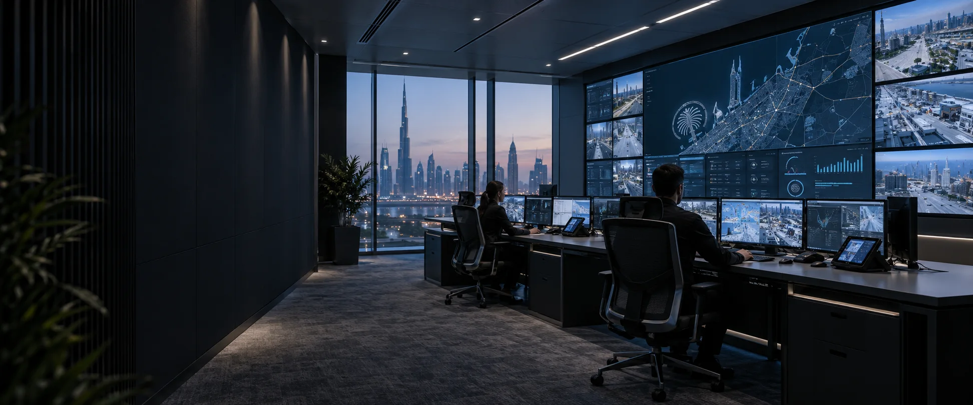
Concept visualisation of a modern Dubai control room with operator desks and a large video wall
Solution 09 / 10

AV systems integration · Dubai & the UAE

Control Rooms

Clarity when every decision counts.

Bring operational information, live sources and the people who use them into one coordinated environment.

  • Consultation
  • Design
  • Integration
  • Support
From the brief
to a working system
See how
it works
  • A shared picture

    Bring permitted information into view.

  • Access by role

    Separate viewing, wall layouts and USB control.

  • Designed for people

    Plan around operators and working positions.

  • Room to develop

    Agree capacity and the next stage early.

01 · Choose a starting point

What does your team need to do?

Typical configurations, not fixed packages or completed projects. Each needs validation against your users, sources, operating conditions and site.

02 · Your selected option · CR-01

A shared operational view

Two operators continue working on their own computers while the team sees four agreed information sources on a shared wall. Their two PCs are included in the four-source count.

Change option ↑

Reference design; project validation required. Read the full design notes →

How it works · grouped system view

Four sources, one shared picture

Sources

4 source PCs

Includes the two local operator PCs.

Wall path · from sources

Wall composition

4 capture channels; layouts chosen by an authorised user.

Operators

2 local desks

Local display, keyboard and mouse; no switched KVM.

Local operation
Shared display

4 LCD panels

Four separate panel feeds form the shared wall.

Sources to wall
Separate control roles

Local computer work and wall layout control are separate. Recalling a wall scene does not take over an operator’s PC.

Devices & connections Inspect here
What these groups contain Device IDs and route references

Functional groups simplify the explanation. Repeated IDs denote the same equipment. Exact interfaces, directions and conditions are in the engineering diagram.

4 source PCs

SRC · 4 x source PCs S1 and S2 are the local operator PCs

Wall composition

PROC · 1 x wall compositor 4 capture channels / 4 panel outputs

2 local desks

DESK · 2 x local operator sets monitor + keyboard + mouse; no extra PCs

4 LCD panels

WALL · 4 x LCD panels 2 by 2; FHD per panel assumed

Control, audio and supporting services

PANEL · 1 x layout panel authorised scene user

NET · 1 x management switch 16 ports; 7 used + 1 service

UPS · 1 x UPS system source, desk, control and wall loads sized separately

Routes: Local operation: L03, L04 · Sources to wall: L01, L02. Supporting links: L05, L06, L07, L08.

CR-01 · Shared operational overview

Keep four agreed sources visible while two operators work locally.

Signal flow

Signal flow. Devices, connections and conditions follow the drawing.Open SVG ↗
CR-01 · Signal flowReference design. Four information PCs feed four capture channels and four LCD outputs. Two local operator positions use two of those same PCs. Layout commands and status use a separate management network. No KVM or processor redundancy. Reference design, not a site plan. Rack, 2 PDU, wall mount and cable/PSU sets: separate BOQ lines. UPS does not duplicate the compositor. No switched KVM. Repeated device identifiers refer to the same equipment across views. Equipment illustrations are schematic; labels define quantities.{"sourceHash":"d57319bb4cab516c8e190b53fba01a7c97740a3bcae2f27a3c450541b936a905","view":"signal","nodes":["SRC","PROC","WALL","DESK"],"edges":["L01","L02","L03","L04"]}PIXEL COMMAND SOLUTIONS / CR-01 / SIGNAL FLOWSignal flowREFERENCE DESIGN · PROJECT VALIDATION REQUIREDSRC → PROC: 4 HDMI feeds; 1080p60 assumed4 HDMI feedsPROC → WALL: 4 separate panel feeds4 separate panel feedsSRC → DESK: 2 additional local display outputs2 additional localdisplay outputsDESK → SRC: local keyboard and mouse USBlocal keyboard andmouse USB4 x source PCs S1 and S2 are the local operator PCsSRC4 x source PCs1 x wall compositor 4 capture channels / 4 panel outputsPROC1 x wall compositor4 x LCD panels 2 by 2; FHD per panel assumedWALL4 x LCD panels2 x local operator sets monitor + keyboard + mouse; no extra PCsDESK2 x local operatorsetsVideo / LED dataUSB / KVM
Devices, connections & design conditions 4 connections
  • Four HDMI sources feed four capture channels.
  • Four separate outputs drive the LCD panels.
  • Two local desks use two of those source PCs; layout control is separate.
SRC
4 x source PCs S1 and S2 are the local operator PCs
PROC
1 x wall compositor 4 capture channels / 4 panel outputs
WALL
4 x LCD panels 2 by 2; FHD per panel assumed
DESK
2 x local operator sets monitor + keyboard + mouse; no extra PCs
  1. SRC → PROC4 HDMI feeds; 1080p60 assumed
  2. PROC → WALL4 separate panel feeds
  3. SRC → DESK2 additional local display outputs
  4. DESK → SRClocal keyboard and mouse USB

Reference design, not a site plan. Rack, 2 PDU, wall mount and cable/PSU sets: separate BOQ lines. UPS does not duplicate the compositor. No switched KVM.

Control & status

Signal flow. Devices, connections and conditions follow the drawing.Open SVG ↗
CR-01 · Control & statusReference design. Four information PCs feed four capture channels and four LCD outputs. Two local operator positions use two of those same PCs. Layout commands and status use a separate management network. No KVM or processor redundancy. Reference design, not a site plan. Rack, 2 PDU, wall mount and cable/PSU sets: separate BOQ lines. UPS does not duplicate the compositor. No switched KVM. Repeated device identifiers refer to the same equipment across views. Equipment illustrations are schematic; labels define quantities.{"sourceHash":"d57319bb4cab516c8e190b53fba01a7c97740a3bcae2f27a3c450541b936a905","view":"control","nodes":["PROC","WALL","PANEL","NET","UPS"],"edges":["L05","L06","L07","L08"]}PIXEL COMMAND SOLUTIONS / CR-01 / CONTROL & STATUSControl & statusREFERENCE DESIGN · PROJECT VALIDATION REQUIREDPANEL ↔ NET: IP: commands / active stateIP: commands / activestateNET ↔ PROC: IP: presets / input loss / display statusIP: presets / inputloss / display statusNET ↔ WALL: IP: panel control and statusIP: panel control andstatusUPS → NET: power status; mains circuits omittedpower status1 x wall compositor 4 capture channels / 4 panel outputsPROC1 x wall compositor4 x LCD panels 2 by 2; FHD per panel assumedWALL4 x LCD panels1 x layout panel authorised scene userPANEL1 x layout panel1 x management switch 16 ports; 7 used + 1 serviceNET1 x management switch1 x UPS system source, desk, control and wall loads sized separatelyUPS1 x UPS systemControl / status
Devices, connections & design conditions 4 connections
  • Four HDMI sources feed four capture channels.
  • Four separate outputs drive the LCD panels.
  • Two local desks use two of those source PCs; layout control is separate.
PROC
1 x wall compositor 4 capture channels / 4 panel outputs
WALL
4 x LCD panels 2 by 2; FHD per panel assumed
PANEL
1 x layout panel authorised scene user
NET
1 x management switch 16 ports; 7 used + 1 service
UPS
1 x UPS system source, desk, control and wall loads sized separately
  1. PANEL ↔ NETIP: commands / active state
  2. NET ↔ PROCIP: presets / input loss / display status
  3. NET ↔ WALLIP: panel control and status
  4. UPS → NETpower status; mains circuits omitted

Reference design, not a site plan. Rack, 2 PDU, wall mount and cable/PSU sets: separate BOQ lines. UPS does not duplicate the compositor. No switched KVM.

Typical architecture · not a project drawing

03 · Scope & limits

What is included. What needs agreement.

System composition

Four source PCs, two desk monitor/keyboard/mouse sets, one compositor with four simultaneous capture channels and four panel outputs, four LCD panels, one layout-control panel and one management switch. Mounts, rack distribution, cabling and a separately sized UPS system complete the example.

Equipment schedule · 4 groups

Example quantities, not an approved procurement schedule. Catalogue links provide component specifications; they do not confirm system compatibility or availability.

LCD wall and mounting
Four panels for CR-01 or CR-02

Project selection; verify duty rating, geometry and service access

Wall composition and capture
1 compositor; 4 capture inputs / 4 panel outputs

Video processing; verify simultaneous resources and licences

Video processing →
Operator equipment and controls
2 local desk sets; 1 wall-layout panel

Project selection against roles, application and USB policy

Power and installation
UPS system, racks, PDU, mounts and cabling

Separate load, autonomy, heat and installation schedules

Browse equipment specifications →

What we need to demonstrate

Read four real sources, recall routine/incident layouts and identify source loss while local work continues Verify the agreed protected loads, configuration restore and defined failure behaviour.

Handover evidence: Content/readability record, preset list and recovery observations Power schedule, restore record and a list of remaining single points of failure.

These are planned project checks. The reference configuration has not passed physical system acceptance.

Discuss this option · CR-01
02 · Your selected option · CR-02

Controlled access to remote PCs

Four operators select from six source PCs. Each desk receives one selected picture and can request keyboard and mouse control where its role permits.

Change option ↑

Reference design; permissions and routing validation required. Read the full design notes →

How it works · grouped system view

Choose a PC. View it. Request control.

Sources

6 source PCs

HDMI and USB connect to six encoders. Source LANs stay separate.

Distribution

Managed AV network

One switch carries media, authorised USB and control.

Two paths from this AV network

Operators

4 operator desks

One receiver, powered USB hub and monitor per desk. One selected PC.

Video + authorised USB ↔
Shared display

2 sources on the wall

Two wall receivers → compositor → four LCD panels. Video only.

Two video streams →
Who can view, and who can control?

The access controller verifies the route and grants one USB owner per PC. Other authorised users may view. Wall-layout rights never grant USB control.

Devices & connections Inspect here
What these groups contain Device IDs and route references

Functional groups simplify the explanation. Repeated IDs denote the same equipment. Exact interfaces, directions and conditions are in the engineering diagram.

6 source PCs

SRC · 6 x source PCs HDMI out + USB host; source LAN stays separate

ENC · 6 x AV/KVM encoders USB DEVICE port connects to source PC

Managed AV network

NET · 1 x managed AV/control switch 48 ports; 24 used + 1 service; multicast + USB

4 operator desks

RX · 4 x desk receivers HDMI out; USB HOST to peripherals

HUB · 4 x powered USB hubs one per desk; approved keyboard / mouse only

DESK · 4 x operator desk sets one monitor and one selected PC per desk

2 sources on the wall

WRX · 2 x wall receivers video only; no USB route or peripheral

PROC · 1 x wall compositor 2 capture channels / 4 panel outputs

WALL · 4 x LCD panels 2 by 2; TWO sources at once

Control, audio and supporting services

UI · 4 x operator access panels login; request; source / owner / grant status

PANEL · 1 x wall-layout panel wall rights do not grant USB control

CTRL · 1 x routing and access controller roles; one USB owner per PC; licences included

UPS · 1 x UPS system all agreed loads; power status via switch

Routes: Video + authorised USB ↔: L01, L02, L03, L04, L05, L06, L07 · Two video streams →: L01, L03, L08, L09, L10. Supporting links: L11, L12, L13, L14, L15, L16.

CR-02 · Authorised KVM operations

Give four operators controlled access to six PCs, with two selected feeds on the wall.

Signal flow

Signal flow. Devices, connections and conditions follow the drawing.Open SVG ↗
CR-02 · Signal flowSame devices, connection identities and directions as the engineering model. Select a connection or device for its complete description.L01: SRC → ENC. 6 HDMI source feedsL01L02: ENC ↔ SRC. USB: source host to endpoint DEVICEL02L03: ENC ↔ NET. 1 GbE per endpoint: media / USB / controlL03L04: NET ↔ RX. 4 selected AV and authorised USB routesL04L05: RX → DESK. 4 HDMI desk feedsL05 · HDMI to desksL06: RX ↔ HUB. USB HOSTL06L07: HUB ↔ DESK. keyboard / mouse USBL07L08: NET → WRX. 2 selected video streamsL08L09: WRX → PROC. 2 HDMI inputsL09L10: PROC → WALL. 4 panel outputsL106 x source PCs HDMI out + USB host; source LAN stays separateSRC6 source PCsHDMI + USB host6 x AV/KVM encoders USB DEVICE port connects to source PCENC6 encodersAV / KVM endpoints1 x managed AV/control switch 48 ports; 24 used + 1 service; multicast + USBNET1 managed switchMedia / USB / control4 x desk receivers HDMI out; USB HOST to peripheralsRX4 desk receiversHDMI + USB HOST4 x powered USB hubs one per desk; approved keyboard / mouse onlyHUB4 powered hubsKeyboard / mouse4 x operator desk sets one monitor and one selected PC per deskDESK4 operator desks1 monitor per desk2 x wall receivers video only; no USB route or peripheralWRX2 wall receiversVideo only1 x wall compositor 2 capture channels / 4 panel outputsPROC1 wall compositor2 captures / 4 outputs4 x LCD panels 2 by 2; TWO sources at onceWALL4 LCD panels2 sources at onceSignal flow · connection IDs match the schedule · reference design, project validation required
Devices, connections & design conditions 10 connections
  • Six encoders feed four desk receivers and two wall receivers.
  • The wall receives two sources at once.
  • The controller confirms the video route and exclusive USB ownership before granting control.
SRC
6 x source PCs HDMI out + USB host; source LAN stays separate
ENC
6 x AV/KVM encoders USB DEVICE port connects to source PC
NET
1 x managed AV/control switch 48 ports; 24 used + 1 service; multicast + USB
RX
4 x desk receivers HDMI out; USB HOST to peripherals
HUB
4 x powered USB hubs one per desk; approved keyboard / mouse only
DESK
4 x operator desk sets one monitor and one selected PC per desk
WRX
2 x wall receivers video only; no USB route or peripheral
PROC
1 x wall compositor 2 capture channels / 4 panel outputs
WALL
4 x LCD panels 2 by 2; TWO sources at once
  1. SRC → ENC6 HDMI source feeds
  2. ENC ↔ SRCUSB: source host to endpoint DEVICE
  3. ENC ↔ NET1 GbE per endpoint: media / USB / control
  4. NET ↔ RX4 selected AV and authorised USB routes
  5. RX → DESK4 HDMI desk feeds
  6. RX ↔ HUBUSB HOST
  7. HUB ↔ DESKkeyboard / mouse USB
  8. NET → WRX2 selected video streams
  9. WRX → PROC2 HDMI inputs
  10. PROC → WALL4 panel outputs

Reference design. Dashed links are logical control sessions over the same switch. SIX-WALL option: add 4 wall receivers AND 4 capture channels; total 16 endpoints. One processor, controller and switch. Infrastructure is counted separately.

Control & status

Signal flow. Devices, connections and conditions follow the drawing.Open SVG ↗
CR-02 · Control & statusReference design. Six source encoders feed four desk receivers and two wall receivers through one managed network. The wall accepts two simultaneous sources. A separate controller grants and verifies exclusive USB ownership. No processor or switch failover is included. Reference design. Dashed links are logical control sessions over the same switch. SIX-WALL option: add 4 wall receivers AND 4 capture channels; total 16 endpoints. One processor, controller and switch. Infrastructure is counted separately. Repeated device identifiers refer to the same equipment across views. Equipment illustrations are schematic; labels define quantities.{"sourceHash":"02f743712b7dbea776fa47f08612e19955b7ba9166f952b2db46046f881ec809","view":"control","nodes":["NET","PROC","WALL","UI","PANEL","CTRL","UPS"],"edges":["L11","L12","L13","L14","L15","L16"]}PIXEL COMMAND SOLUTIONS / CR-02 / CONTROL & STATUSControl & statusREFERENCE DESIGN · PROJECT VALIDATION REQUIREDUI ↔ CTRL: authenticated requests / confirmed stateauthenticated requests/ confirmed statePANEL ↔ CTRL: layout request / active statelayout request / activestateCTRL ↔ NET: IP via switch: video route and USB pairing; verify before grantIP via switch: videoroute and USB pairingCTRL ↔ PROC: IP via switch: presets / statusIP via switch: presets/ statusNET ↔ WALL: IP: panel status / controlIP: panel status /controlUPS → NET: IP statusIP status1 x managed AV/control switch 48 ports; 24 used + 1 service; multicast + USBNET1 x managed AV/controlswitch1 x wall compositor 2 capture channels / 4 panel outputsPROC1 x wall compositor4 x LCD panels 2 by 2; TWO sources at onceWALL4 x LCD panels4 x operator access panels login; request; source / owner / grant statusUI4 x operator accesspanels1 x wall-layout panel wall rights do not grant USB controlPANEL1 x wall-layout panel1 x routing and access controller roles; one USB owner per PC; licences includedCTRL1 x routing and accesscontroller1 x UPS system all agreed loads; power status via switchUPS1 x UPS systemControl / status
Devices, connections & design conditions 6 connections
  • Six encoders feed four desk receivers and two wall receivers.
  • The wall receives two sources at once.
  • The controller confirms the video route and exclusive USB ownership before granting control.
NET
1 x managed AV/control switch 48 ports; 24 used + 1 service; multicast + USB
PROC
1 x wall compositor 2 capture channels / 4 panel outputs
WALL
4 x LCD panels 2 by 2; TWO sources at once
UI
4 x operator access panels login; request; source / owner / grant status
PANEL
1 x wall-layout panel wall rights do not grant USB control
CTRL
1 x routing and access controller roles; one USB owner per PC; licences included
UPS
1 x UPS system all agreed loads; power status via switch
  1. UI ↔ CTRLauthenticated requests / confirmed state
  2. PANEL ↔ CTRLlayout request / active state
  3. CTRL ↔ NETIP via switch: video route and USB pairing; verify before grant
  4. CTRL ↔ PROCIP via switch: presets / status
  5. NET ↔ WALLIP: panel status / control
  6. UPS → NETIP status

Reference design. Dashed links are logical control sessions over the same switch. SIX-WALL option: add 4 wall receivers AND 4 capture channels; total 16 endpoints. One processor, controller and switch. Infrastructure is counted separately.

Typical architecture · not a project drawing

03 · Scope & limits

What is included. What needs agreement.

System composition

Six source PCs, six source encoders, four desk receivers, two wall receivers, four desk monitor/keyboard/mouse sets with powered USB hubs, four operator access panels, one routing and access controller, one wall-layout panel, one compositor with two capture channels and four panel outputs, four LCD panels and one managed AV/control switch. Power and installation infrastructure are counted separately.

Equipment schedule · 5 groups

Example quantities, not an approved procurement schedule. Catalogue links provide component specifications; they do not confirm system compatibility or availability.

LCD wall and mounting
Four panels for CR-01 or CR-02

Project selection; verify duty rating, geometry and service access

Wall composition and capture
1 compositor; 2 capture inputs / 4 panel outputs

Video processing; verify simultaneous resources and licences

Video processing →
AV/KVM endpoints and network
Six encoders and six receivers for CR-02

AV over IP and signal extension; USB capability needs explicit selection

AV over IP →signal extension →
Operator equipment and controls
4 desk sets and access panels; 1 routing controller and 1 wall-layout panel

Project selection against roles, application and USB policy

Power and installation
UPS system, racks, PDU, mounts and cabling

Separate load, autonomy, heat and installation schedules

Browse equipment specifications →

What we need to demonstrate

Exercise all permitted and denied source requests; contend for one PC; release control; route two wall sources independently Verify the agreed protected loads, configuration restore and defined failure behaviour.

Handover evidence: Role matrix, route/ownership log, USB compatibility list and measured switching results Power schedule, restore record and a list of remaining single points of failure.

These are planned project checks. The reference configuration has not passed physical system acceptance.

Discuss this option · CR-02

02 · Your selected option · CR-03

A briefing with a remote team

Two technical operators prepare information for a local meeting and one remote call. Their PCs form part of the six information sources; a separate conferencing PC runs the call.

Change option ↑

Reference design; independent output and call validation required. Read the full design notes →

How it works · grouped system view

The room sees more than the remote call

Sources

6 information PCs

Two also serve the local operators. Information feeds are silent.

Composition

Independent programmes

One compositor: six information inputs + the incoming call.

Two independent programmes from this compositor

Remote participants

SHARE → remote call

Approved sources only, through a separate content capture.

SHARE: no call return →
Shared display

WALL → local display

The local LED wall can show sources and the incoming call.

WALL: sources + return →
Keep the return out of the outgoing programme

Staff preview, then explicitly start or stop sharing. Room microphones go through AEC; call-return audio feeds the room and its AEC reference, and is excluded from the call send.

Devices & connections Inspect here
What these groups contain Device IDs and route references

Functional groups simplify the explanation. Repeated IDs denote the same equipment. Exact interfaces, directions and conditions are in the engineering diagram.

6 information PCs

SRC · 6 x information PCs includes the two local technical PCs; silent feeds

DESK · 2 x local operator sets monitor + keyboard + mouse; no extra PCs

Independent programmes

PROC · 1 x compositor 7 capture channels / 2 independent output programmes

SHARE → remote call

SHARE · 1 x HDMI-to-USB capture SHARE output only; excludes C7 call return

UC · 1 x conferencing PC set own local monitor; camera + content + USB audio

SERVICE · 1 x client conferencing service client network / WAN; outside AV management LAN

CAM · 1 x PTZ camera SDI video; IP preset control

CAP · 1 x SDI-to-USB capture camera input; selected USB format

WALL → local display

LED · 1 x LED display package sender + receiving cards + surface + PSU

Control, audio and supporting services

MIC · 2 x wired microphone zones initial layout; room coverage to be tested

DSP · 1 x AEC audio processor mic send / call return / AEC reference

AMP · 1 x amplifier selected line and load type

SPK · 2 x room loudspeakers call return only; no local mic reinforcement

PANEL · 1 x layout / room panel share and mute state stay in UC app unless API is validated

NET · 1 x management switch 16 ports; 6 used + 1 service

UPS · 1 x UPS system agreed source, wall, control and meeting loads

Routes: SHARE: no call return →: L01, L05, L06, L10 · WALL: sources + return →: L01, L07, L04. Supporting links: L11, L12, L13, L14, L15, L16, L17, L18, L19, L20, L21, L22.

CR-03 · Hybrid situation briefing

Share approved briefing content and speech with a remote team.

Video & data

Signal flow. Devices, connections and conditions follow the drawing.Open SVG ↗
CR-03 · Video & dataSame devices, connection identities and directions as the engineering model. Select a connection or device for its complete description.L01: SRC → PROC. 6 HDMI: C1 to C6L01 · 6 HDMIL02: SRC → DESK. 2 separate local display outputsL02L03: DESK → SRC. local keyboard and mouse USBL03L04: PROC → LED. O1 WALL; LED pixel map by designL04L05: PROC → SHARE. O2 SHARE; independent 1080p30 programmeL05 · independent SHAREL06: SHARE → UC. USB video: approved contentL06L07: UC → PROC. HDMI: C7 call return; separate from UC local UIL07 · call return; excluded from SHAREL08: CAM → CAP. SDIL08L09: CAP → UC. USB camera videoL09 · USBL10: UC ↔ SERVICE. IP: meeting media and signallingL106 x information PCs includes the two local technical PCs; silent feedsSRC6 information PCsSilent source feeds2 x local operator sets monitor + keyboard + mouse; no extra PCsDESK2 local desksNo additional PCs1 x compositor 7 capture channels / 2 independent output programmesPROC1 compositor7 inputs / 2 outputs1 x LED display package sender + receiving cards + surface + PSULED1 LED packageLocal WALL1 x HDMI-to-USB capture SHARE output only; excludes C7 call returnSHARE1 content captureIndependent SHARE1 x conferencing PC set own local monitor; camera + content + USB audioUC1 conferencing PCCamera + content1 x client conferencing service client network / WAN; outside AV management LANSERVICEConferencing serviceClient network / WAN1 x PTZ camera SDI video; IP preset controlCAM1 PTZ cameraSDI video1 x SDI-to-USB capture camera input; selected USB formatCAP1 camera captureSDI → USBVideo & data · connection IDs match the schedule · reference design, project validation required
Devices, connections & design conditions 10 connections
  • Six information feeds and one call return enter the compositor.
  • The independent SHARE programme excludes the call return.
  • Room microphones feed the call; call return feeds the room and AEC reference.
SRC
6 x information PCs includes the two local technical PCs; silent feeds
DESK
2 x local operator sets monitor + keyboard + mouse; no extra PCs
PROC
1 x compositor 7 capture channels / 2 independent output programmes
LED
1 x LED display package sender + receiving cards + surface + PSU
SHARE
1 x HDMI-to-USB capture SHARE output only; excludes C7 call return
UC
1 x conferencing PC set own local monitor; camera + content + USB audio
SERVICE
1 x client conferencing service client network / WAN; outside AV management LAN
CAM
1 x PTZ camera SDI video; IP preset control
CAP
1 x SDI-to-USB capture camera input; selected USB format
  1. SRC → PROC6 HDMI: C1 to C6
  2. SRC → DESK2 separate local display outputs
  3. DESK → SRClocal keyboard and mouse USB
  4. PROC → LEDO1 WALL; LED pixel map by design
  5. PROC → SHAREO2 SHARE; independent 1080p30 programme
  6. SHARE → UCUSB video: approved content
  7. UC → PROCHDMI: C7 call return; separate from UC local UI
  8. CAM → CAPSDI
  9. CAP → UCUSB camera video
  10. UC ↔ SERVICEIP: meeting media and signalling

Reference design, not a completed installation. Independent composition and camera + external content workflow require FAT. Power, mounts, rack, 2 PDU and cable/PSU sets are separate BOQ lines. No failover.

Audio & return paths

Signal flow. Devices, connections and conditions follow the drawing.Open SVG ↗
CR-03-audio · Audio & return pathsSame devices, connection identities and directions as the engineering model. Select a connection or device for its complete description.L11: MIC → DSP. 2 balanced mic inputsL11 · micsL12: DSP → UC. USB send: mics after AEC; no return audioL12 · AEC speech → callL13: UC → DSP. USB receive: call returnL13 · call → room / AEC ref.L14: DSP → AMP. mono line output: return mixL14L15: AMP → SPK. speaker circuit: matched loadL15L16: DSP → DSP. internal AEC reference: actual room return mixL16 · internal AEC reference2 x wired microphone zones initial layout; room coverage to be testedMIC2 microphone zonesCoverage to be tested1 x AEC audio processor mic send / call return / AEC referenceDSP1 AEC processorSend / return / ref.1 x conferencing PC set own local monitor; camera + content + USB audioUC1 conferencing PCSame PC as video1 x amplifier selected line and load typeAMP1 amplifierMatched line / load2 x room loudspeakers call return only; no local mic reinforcementSPK2 room speakersCall return onlyAudio & return paths · connection IDs match the schedule · reference design, project validation required
Devices, connections & design conditions 6 connections
  • Six information feeds and one call return enter the compositor.
  • The independent SHARE programme excludes the call return.
  • Room microphones feed the call; call return feeds the room and AEC reference.
UC
1 x conferencing PC set own local monitor; camera + content + USB audio
MIC
2 x wired microphone zones initial layout; room coverage to be tested
DSP
1 x AEC audio processor mic send / call return / AEC reference
AMP
1 x amplifier selected line and load type
SPK
2 x room loudspeakers call return only; no local mic reinforcement
  1. MIC → DSP2 balanced mic inputs
  2. DSP → UCUSB send: mics after AEC; no return audio
  3. UC → DSPUSB receive: call return
  4. DSP → AMPmono line output: return mix
  5. AMP → SPKspeaker circuit: matched load
  6. DSP → DSPinternal AEC reference: actual room return mix

Reference design, not a completed installation. Independent composition and camera + external content workflow require FAT. Power, mounts, rack, 2 PDU and cable/PSU sets are separate BOQ lines. No failover.

Control & status

Signal flow. Devices, connections and conditions follow the drawing.Open SVG ↗
CR-03 · Control & statusReference design. Six information sources and one call return feed a compositor. The local LED wall and outgoing programme are independently composed. The outgoing programme excludes the call return. Camera and programme use separate USB captures. DSP sends room microphones to the call and uses the incoming audio as AEC reference and room playback. Reference design, not a completed installation. Independent composition and camera + external content workflow require FAT. Power, mounts, rack, 2 PDU and cable/PSU sets are separate BOQ lines. No failover. Repeated device identifiers refer to the same equipment across views. Equipment illustrations are schematic; labels define quantities.{"sourceHash":"92ddf731337343df6365a8c47071894e541eae9bce1160441ccb43c4d731a606","view":"control","nodes":["PROC","LED","CAM","DSP","PANEL","NET","UPS"],"edges":["L17","L18","L19","L20","L21","L22"]}PIXEL COMMAND SOLUTIONS / CR-03 / CONTROL & STATUSControl & statusREFERENCE DESIGN · PROJECT VALIDATION REQUIREDPANEL ↔ NET: IP managementIP managementNET ↔ PROC: IP: layouts / input and output stateIP: layouts / input andoutput stateNET ↔ CAM: IP: presets / statusIP: presets / statusNET ↔ DSP: IP: audio control / statusIP: audio control /statusNET ↔ LED: IP: sender control / statusIP: sender control /statusUPS → NET: IP power statusIP power status1 x compositor 7 capture channels / 2 independent output programmesPROC1 x compositor1 x LED display package sender + receiving cards + surface + PSULED1 x LED displaypackage1 x PTZ camera SDI video; IP preset controlCAM1 x PTZ camera1 x AEC audio processor mic send / call return / AEC referenceDSP1 x AEC audioprocessor1 x layout / room panel share and mute state stay in UC app unless API is validatedPANEL1 x layout / roompanel1 x management switch 16 ports; 6 used + 1 serviceNET1 x management switch1 x UPS system agreed source, wall, control and meeting loadsUPS1 x UPS systemControl / status
Devices, connections & design conditions 6 connections
  • Six information feeds and one call return enter the compositor.
  • The independent SHARE programme excludes the call return.
  • Room microphones feed the call; call return feeds the room and AEC reference.
PROC
1 x compositor 7 capture channels / 2 independent output programmes
LED
1 x LED display package sender + receiving cards + surface + PSU
CAM
1 x PTZ camera SDI video; IP preset control
DSP
1 x AEC audio processor mic send / call return / AEC reference
PANEL
1 x layout / room panel share and mute state stay in UC app unless API is validated
NET
1 x management switch 16 ports; 6 used + 1 service
UPS
1 x UPS system agreed source, wall, control and meeting loads
  1. PANEL ↔ NETIP management
  2. NET ↔ PROCIP: layouts / input and output state
  3. NET ↔ CAMIP: presets / status
  4. NET ↔ DSPIP: audio control / status
  5. NET ↔ LEDIP: sender control / status
  6. UPS → NETIP power status

Reference design, not a completed installation. Independent composition and camera + external content workflow require FAT. Power, mounts, rack, 2 PDU and cable/PSU sets are separate BOQ lines. No failover.

Typical architecture · not a project drawing

03 · Scope & limits

What is included. What needs agreement.

System composition

Six source PCs, two desk monitor/keyboard/mouse sets, one compositor with seven simultaneous capture channels and two independently composed outputs, one LED display package, one conferencing PC with its own control monitor, one PTZ camera and SDI-to-USB capture, one HDMI-to-USB programme capture, two wired microphone zones, one echo-cancelling audio processor, one amplifier and two room loudspeakers. A control panel, management switch, conferencing service and installation/power infrastructure support the system.

Equipment schedule · 6 groups

Example quantities, not an approved procurement schedule. Catalogue links provide component specifications; they do not confirm system compatibility or availability.

Fine-pitch LED system
One complete surface, sender, receivers and power system for CR-03

Fine-pitch LED; final pixel and port map required

Fine-pitch LED →
Wall composition and capture
1 compositor; 7 capture inputs / 2 independently composed outputs

Video processing; verify simultaneous resources and licences

Video processing →
Operator equipment and controls
2 local desk sets; 1 room control panel

Project selection against roles, application and USB policy

Meeting capture and microphones
CR-03 camera, two captures and two microphone zones

Microphones; camera/capture selection by tested interfaces

Microphones →
Meeting audio
CR-03 AEC processor, amplifier and two speakers

Audio processing, amplifiers and speakers

Audio processing →amplifiers →speakers →
Power and installation
UPS system, racks, PDU, mounts and cabling

Separate load, autonomy, heat and installation schedules

Browse equipment specifications →

What we need to demonstrate

Show the local wall and a different outgoing view; change the incoming call; speak from both microphone zones and the remote endpoint Verify the agreed protected loads, configuration restore and defined failure behaviour.

Handover evidence: Call test record, outgoing-source allowlist and audio/video loop checks Power schedule, restore record and a list of remaining single points of failure.

These are planned project checks. The reference configuration has not passed physical system acceptance.

Discuss this option · CR-03

04 · From brief to handover

Agree the workflow before choosing the hardware.

The final design needs your source list, access rules, viewing positions and IT requirements. Software and interfaces are verified within an agreed scope.

  1. 01

    Scope and architecture

    Agree operators, shifts, sources and simultaneous views. Record control rights, sharing boundaries and required availability. Select the configuration.

  2. 02

    Design and approval

    Issue wall and desk layouts, signal and control diagrams, source/permission matrices, network requirements and power/heat schedules. Define additional resilience where required.

  3. 03

    Selection and supply

    Confirm display, compositor, endpoints, capture and licence compatibility. Validate the critical KVM or conferencing workflow before releasing the final order.

  4. 04

    Installation and programming

    Install and label the system, connect approved sources, configure layouts and operator rights, and set up the selected software. Where CraftWall is selected, configure its approved sources, scenes and roles; test any specified alarm or identity integration.

  5. 05

    Commissioning and tests

    Run real operator tasks, denied-access checks, source changes and recovery tests. For CR-03, verify the remote picture and audio; test each duplicated path if resilience is included.

  6. 06

    Handover

    Train operators and administrators. Deliver as-built diagrams, source/permission schedules, configuration backups, test results and an agreed maintenance and recovery procedure.

Detailed stages and deliverables →

05 · Team experience

Related work, with its own brief.

These documented projects are separate from the reference designs (CR-01, CR-02, CR-03). Each records its own scope and outcome.

Illustrative visualisation of an operator in front of a multi-window video wall, not the project site
Illustrative visual
RC-03
Control rooms

Duty-service video wall

A video wall giving a civil protection duty service a shared operational picture.

Display
Duty-service video wall

Completed video wall installation.

Illustrative visualisation of an operator desk facing a video wall of maps and camera views, not the project site
Illustrative visual
RC-06
Control rooms

Dispatch information display system

Visual information for the duty team of a unified dispatch service.

Display
Video wall for the dispatch room

Completed information display system.

Explore our team’s project experience →

Planning a specification?

The full technical notes retain application scenarios, detailed architecture, design parameters, interfaces, standards, available project drawings and questions to resolve.

Design requirements →IT and building interfaces →Project drawing →Inputs and FAQ →

CraftWall for sources, scenes and operator control. →

Next step

Tell us what your operators need to do.

Send a room layout, a source list and the roles that need to view, control or share information. Your selected configuration will be included in the enquiry.