02 · Your selected option · EDU-01
Classroom presentation
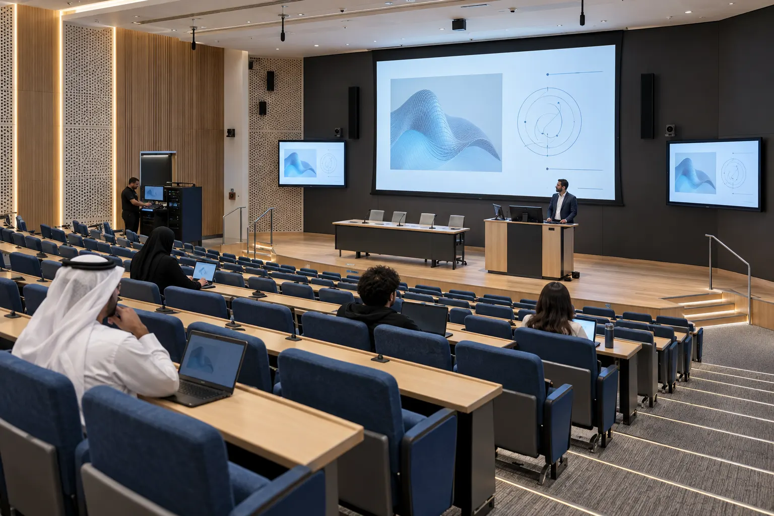
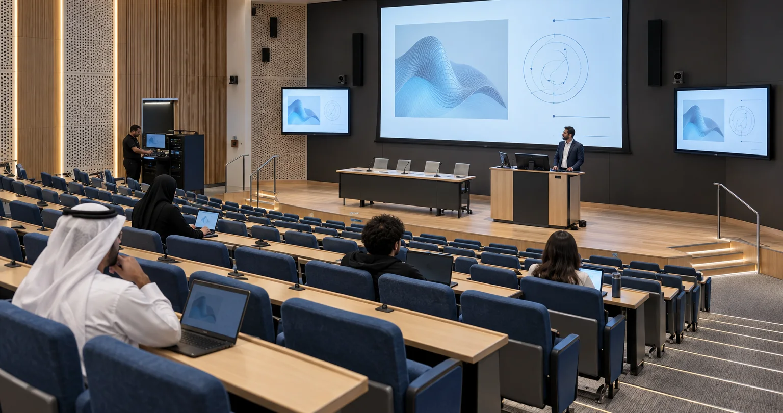
A lecturer presents from the teaching PC or an agreed guest connection to students in the room.
Reference design · project selection and tests required. Read the full design notes →
How it works · functional groups
Show the material. Make speech clear.
Teaching material
Teaching PC
Or an agreed guest connection.
Source selection
Select one presentation input.
Main display
Shared material for the room.
Room sound
Speech + content
One lecturer microphone and source audio.
Room mix
Process speech and playback separately.
Listening area
Amplifier and two starting loudspeakers.
The room panel controls sources, display power, sound level and mute. This option has no camera capture, recording or remote call.
Devices & connections Inspect here
What these groups contain Devices and connection references
Rows explain related paths. A group can include parallel outputs; the full drawing shows individual devices, directions and conditions. Repeated IDs refer to the same equipment.
Teaching material
- Teaching PC
PC · Teaching PC ×1 · Includes operator monitor
- Source selection
SW · Presentation switcher ×1 · 2 inputs / 1 output · Stereo audio extraction
- Main display
SCREEN · Main display ×1
Connections: L01, L02.
Room sound
- Speech + content
MIC · Lecturer microphone ×1
SW · Presentation switcher ×1 · 2 inputs / 1 output · Stereo audio extraction
- Room mix
DSP · Audio processor ×1 · 3 analogue inputs used · Room mix: mono
- Listening area
AMP · Amplifier ×1
SPK · Loudspeakers ×2 · Initial layout assumption
Connections: L03, L04, L05, L06.
Other devices, controls and supporting services
- CTRL · Integrated panel/controller ×1
- NOTE · REFERENCE DESIGN · PER ROOM · Solid: media. Dashed: control/status. · Room switch ×1 + installation set ×1 support these routes. · Input 2 is reserved for a guest source; no second source supplied. · No capture, conferencing or camera included.
EDU-01
Presentation video reaches the main display; extracted programme audio and the lecturer microphone feed the room sound system.
Signal flow
All 6 connections · 7 devices and services
Choose a connection to read its endpoints, direction and interface. Repeated device IDs refer to the same equipment across views.
From · PCTeaching PC ×1 Includes operator monitor
To · SWPresentation switcher ×1 2 inputs / 1 output Stereo audio extraction
Direction: source → destination · HDMI
From · SWPresentation switcher ×1 2 inputs / 1 output Stereo audio extraction
To · SCREENMain display ×1
Direction: source → destination · HDMI
From · SWPresentation switcher ×1 2 inputs / 1 output Stereo audio extraction
To · DSPAudio processor ×1 3 analogue inputs used Room mix: mono
Direction: source → destination · Analogue L/R
From · MICLecturer microphone ×1
To · DSPAudio processor ×1 3 analogue inputs used Room mix: mono
Direction: source → destination · Analogue mic
From · DSPAudio processor ×1 3 analogue inputs used Room mix: mono
To · AMPAmplifier ×1
Direction: source → destination · Line output 1
From · AMPAmplifier ×1
To · SPKLoudspeakers ×2 Initial layout assumption
Direction: source → destination · Speaker lines
PC · Teaching PC ×1 Includes operator monitor
Connections: L01. Repeated device IDs refer to the same equipment.
SW · Presentation switcher ×1 2 inputs / 1 output Stereo audio extraction
Connections: L01, L02, L03. Repeated device IDs refer to the same equipment.
SCREEN · Main display ×1
Connections: L02. Repeated device IDs refer to the same equipment.
DSP · Audio processor ×1 3 analogue inputs used Room mix: mono
Connections: L03, L04, L05. Repeated device IDs refer to the same equipment.
MIC · Lecturer microphone ×1
Connections: L04. Repeated device IDs refer to the same equipment.
AMP · Amplifier ×1
Connections: L05, L06. Repeated device IDs refer to the same equipment.
SPK · Loudspeakers ×2 Initial layout assumption
Connections: L06. Repeated device IDs refer to the same equipment.
Devices, connections & design conditions 6 connections
- Teaching PC ×1; Includes operator monitor → Presentation switcher ×1; 2 inputs / 1 output; Stereo audio extraction: HDMI.
- Presentation switcher ×1; 2 inputs / 1 output; Stereo audio extraction → Main display ×1: HDMI.
- Presentation switcher ×1; 2 inputs / 1 output; Stereo audio extraction → Audio processor ×1; 3 analogue inputs used; Room mix: mono: Analogue L/R.
- Lecturer microphone ×1 → Audio processor ×1; 3 analogue inputs used; Room mix: mono: Analogue mic.
- Audio processor ×1; 3 analogue inputs used; Room mix: mono → Amplifier ×1: Line output 1.
- Amplifier ×1 → Loudspeakers ×2; Initial layout assumption: Speaker lines.
- Integrated panel/controller ×1 → Presentation switcher ×1; 2 inputs / 1 output; Stereo audio extraction: RS-232: source (control/status/authorisation).
- Integrated panel/controller ×1 → Main display ×1: RS-232: power (control/status/authorisation).
- Integrated panel/controller ×1 → Audio processor ×1; 3 analogue inputs used; Room mix: mono: IP: level / mute (control/status/authorisation).
- Audio processor ×1; 3 analogue inputs used; Room mix: mono → Integrated panel/controller ×1: IP: actual state (control/status/authorisation).
- PC
- Teaching PC ×1 Includes operator monitor
- SW
- Presentation switcher ×1 2 inputs / 1 output Stereo audio extraction
- SCREEN
- Main display ×1
- DSP
- Audio processor ×1 3 analogue inputs used Room mix: mono
- MIC
- Lecturer microphone ×1
- AMP
- Amplifier ×1
- SPK
- Loudspeakers ×2 Initial layout assumption
- PC → SWHDMI
- SW → SCREENHDMI
- SW → DSPAnalogue L/R
- MIC → DSPAnalogue mic
- DSP → AMPLine output 1
- AMP → SPKSpeaker lines
REFERENCE DESIGN · PER ROOM Solid: media. Dashed: control/status. Room switch ×1 + installation set ×1 support these routes. Input 2 is reserved for a guest source; no second source supplied. No capture, conferencing or camera included.
Control & status
All 4 connections · 4 devices and services
Choose a connection to read its endpoints, direction and interface. Repeated device IDs refer to the same equipment across views.
From · CTRLIntegrated panel/controller ×1
To · SWPresentation switcher ×1 2 inputs / 1 output Stereo audio extraction
Direction: source → destination · RS-232: source
From · CTRLIntegrated panel/controller ×1
To · SCREENMain display ×1
Direction: source → destination · RS-232: power
From · CTRLIntegrated panel/controller ×1
To · DSPAudio processor ×1 3 analogue inputs used Room mix: mono
Direction: source → destination · IP: level / mute
From · DSPAudio processor ×1 3 analogue inputs used Room mix: mono
To · CTRLIntegrated panel/controller ×1
Direction: source → destination · IP: actual state
SW · Presentation switcher ×1 2 inputs / 1 output Stereo audio extraction
Connections: L07. Repeated device IDs refer to the same equipment.
SCREEN · Main display ×1
Connections: L08. Repeated device IDs refer to the same equipment.
DSP · Audio processor ×1 3 analogue inputs used Room mix: mono
Connections: L09, L10. Repeated device IDs refer to the same equipment.
CTRL · Integrated panel/controller ×1
Connections: L07, L08, L09, L10. Repeated device IDs refer to the same equipment.
Devices, connections & design conditions 4 connections
- Teaching PC ×1; Includes operator monitor → Presentation switcher ×1; 2 inputs / 1 output; Stereo audio extraction: HDMI.
- Presentation switcher ×1; 2 inputs / 1 output; Stereo audio extraction → Main display ×1: HDMI.
- Presentation switcher ×1; 2 inputs / 1 output; Stereo audio extraction → Audio processor ×1; 3 analogue inputs used; Room mix: mono: Analogue L/R.
- Lecturer microphone ×1 → Audio processor ×1; 3 analogue inputs used; Room mix: mono: Analogue mic.
- Audio processor ×1; 3 analogue inputs used; Room mix: mono → Amplifier ×1: Line output 1.
- Amplifier ×1 → Loudspeakers ×2; Initial layout assumption: Speaker lines.
- Integrated panel/controller ×1 → Presentation switcher ×1; 2 inputs / 1 output; Stereo audio extraction: RS-232: source (control/status/authorisation).
- Integrated panel/controller ×1 → Main display ×1: RS-232: power (control/status/authorisation).
- Integrated panel/controller ×1 → Audio processor ×1; 3 analogue inputs used; Room mix: mono: IP: level / mute (control/status/authorisation).
- Audio processor ×1; 3 analogue inputs used; Room mix: mono → Integrated panel/controller ×1: IP: actual state (control/status/authorisation).
- SW
- Presentation switcher ×1 2 inputs / 1 output Stereo audio extraction
- SCREEN
- Main display ×1
- DSP
- Audio processor ×1 3 analogue inputs used Room mix: mono
- CTRL
- Integrated panel/controller ×1
- CTRL → SWRS-232: source
- CTRL → SCREENRS-232: power
- CTRL → DSPIP: level / mute
- DSP → CTRLIP: actual state
REFERENCE DESIGN · PER ROOM Solid: media. Dashed: control/status. Room switch ×1 + installation set ×1 support these routes. Input 2 is reserved for a guest source; no second source supplied. No capture, conferencing or camera included.
Typical architecture · not a project drawing
03 · Scope & limits
What is included. What needs agreement.
System composition
One teaching PC, one main display, one presentation switcher with audio extraction, one lecturer microphone, one audio processor, one amplifier, two loudspeakers and one integrated room panel/controller. One managed room switch and a room installation set complete the example. The PC includes its operator monitor; it is separate from the main display.
Equipment schedule · 10 groups
Example quantities, not an approved procurement schedule. Catalogue links provide component specifications; they do not confirm system compatibility or availability.
- Teaching PC, including operator monitor
- 1
Selected with institutional IT
- Main / additional AV displays
- 1 / 0
Display options where LED suits the design; other display types by specification
Display options → - Presentation switching / distribution
- 1
Switching equipment
Switching equipment → - Lecturer / question microphones
- 1 / 0
Microphones
Microphones → - Audio processor
- 1
Mixers and processors
Mixers and processors → - Amplifier / loudspeakers
- 1 / 2
Amplifiers · Loudspeakers
Amplifiers →Loudspeakers → - PTZ cameras / SDI-to-USB capture devices
- 0 / 0
Camera and capture interfaces selected together
- Recorder / recording medium
- 0 / 0
Selected to the capture and retention brief
- Integrated room panel/controller / recording indicator
- 1 / 0
Selected to device control interfaces
- Managed room switch / installation set
- 1 / 1
Network, cabling, mounting and power by project
What we need to demonstrate
Read real slides at agreed seats; hear speech; change source, level and mute.
Handover evidence: Display, sound and control check sheet.
Discuss this option · EDU-01