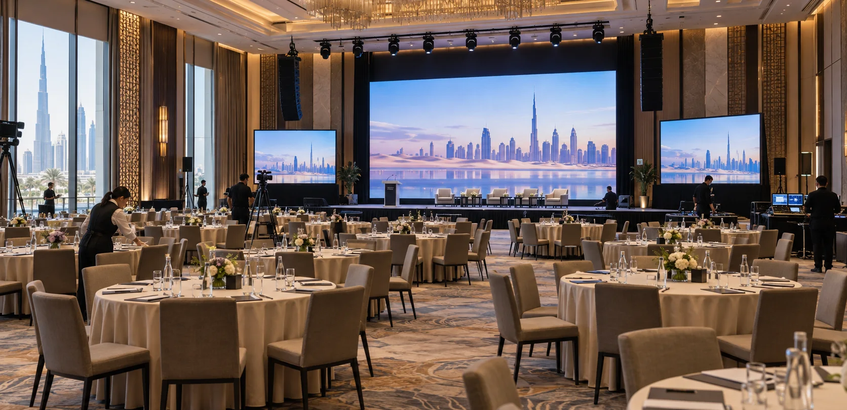
Concept visualisation of an indoor event venue with a stage and AV equipment
Solution 06 / 10

AV systems integration · Dubai & the UAE

Concert & event venues

Bring sound, picture and light together.

Bring sound, video and lighting together for the agreed programme.

  • Consultation
  • Design
  • Integration
  • Support
From the brief
to a working system
See how
it works
  • The programme first

    Define performance and event requirements.

  • Sound & coverage

    Coordinate PA, stage inputs and monitoring.

  • Picture & lighting

    Agree the visual system and control paths.

  • Site coordination

    Plan power, rigging and service access.

01 · Choose a starting point

What does your team need to do?

Typical configurations, not fixed packages or completed projects. Each needs validation against your users, sources, operating conditions and site.

02 · Your selected option · EV-01

Small permanent stage

A venue technician runs speech and a small music programme from one indoor stage.

Change option ↑

Reference design · project selection and system tests required. Read the full design notes →

How it works · functional groups

A technician runs sound and basic stage lighting

Stage sound

Twelve source channels

Eight wired microphones, two DI and two wireless channels.

FOH mixer

House stereo and two independent monitor mixes.

Audience + performers

Powered tops, subwoofers and two stage monitors.

Stage lighting

Venue technician

Select scenes, levels and blackout.

Isolated DMX branches

Four outputs carry the same universe.

Four profile fixtures

Selected optics, mounting and branch termination.

Presentation video is a separately specified option; cameras and recording are not included. PA and lighting counts require coverage and photometric design.

Devices & connections Inspect here
What these groups contain Devices and connection references

Rows explain related paths. A group can include parallel outputs; the full drawing shows individual devices, directions and conditions. Repeated IDs refer to the same equipment.

Stage sound

Twelve source channels

EV01_MIC · 8 x wired microphones

EV01_DI · 2 x DI channels

EV01_RF · 2 x complete wireless channels

EV01_PATCH · 1 x passive multicore · 12 sends / 4 returns

FOH mixer

EV01_MIX · 1 x FOH mixer · 16 mono inputs / 8 line outputs

Audience + performers

EV01_SUB · 2 x powered subwoofers · LPF set locally

EV01_TOP · 2 x powered main speakers · HPF set locally

EV01_MON · 2 x powered stage monitors · 2 independent mono mixes

Connections: L01, L02, L03, L04, L05, L06, L07.

Stage lighting

Venue technician

OP · Venue technician

EV01_LC · 1 x lighting console

Isolated DMX branches

EV01_SPLIT · 1 x isolated splitter · 4 outputs, same universe

Four profile fixtures

EV01_LIGHT · 4 x profile fixtures · optics and mounting included

EV01_TERM · 4 x 120 ohm terminators

Connections: L08, L09, L10, L11.

Other devices, controls and supporting services

  • EV01_PC · 1 x content laptop · customer supplied
  • EV01_PRES · 1 x presentation switcher · 2 inputs / 1 output + audio extraction
  • EV01_LEDPROC · 1 x LED processor
  • EV01_LED · 1 x indoor LED assembly · size and pixels by design
  • EV01_STEREO · 1 x stereo isolation interface
  • MIXREF · Same FOH mixer · local inputs 13-14; total 14/16
  • EV01_VIDINFRA · 1 x display infrastructure allowance
  • EV01_INFRA · 1 x installation allowance · power, supports, cables, supplies
  • POWERREF · Same powered PA, monitors and light
  • NOTE · Project load / route / mounting schedules required
  • EV01_SPARES · 1 x service spares schedule

EV-01 · Small permanent stage

Twelve stage sources feed the house and monitor mixes. Basic lighting has isolated DMX branches. Presentation LED is optional.

AUDIO

Signal flow. Devices, connections and conditions follow the drawing.Open SVG ↗
EV-01 · AUDIOTwelve stage sources, four analogue returns, powered main sound and two monitor mixes. Four independently addressed lighting fixtures. Presentation LED is an optional group. No recording or camera relay in the base scope. Repeated device identifiers refer to the same equipment across views. Equipment illustrations are schematic; labels define quantities.{"sourceHash":"de653cfb8e3523a893bb7f8d4d4cde53a6fbccecee4d19e812f6d53cca2ce4b1","view":"audio","nodes":["EV01_MIC","EV01_PATCH","EV01_DI","EV01_RF","EV01_MIX","EV01_SUB","EV01_TOP","EV01_MON"],"edges":["L01","L02","L03","L04","L05","L06","L07"]}PIXEL COMMAND SOLUTIONS / EV-01 / AUDIOAUDIOREFERENCE DESIGN · PROJECT VALIDATION REQUIREDEV01_MIC → EV01_PATCH: balanced micbalanced micEV01_DI → EV01_PATCH: balanced mic or linebalanced mic or lineEV01_RF → EV01_PATCH: receiver audioreceiver audioEV01_PATCH → EV01_MIX: 12 analogue inputs12 analogue inputsEV01_MIX → EV01_SUB: L/R via returns 1-2L/R via returns 1-2EV01_SUB → EV01_TOP: full-range THRU, L and Rfull-range THRU, L andREV01_MIX → EV01_MON: aux 1-2 via returns 3-4aux 1-2 via returns 3-48 x wired microphonesEV01_MIC8 x wired microphones1 x passive multicore 12 sends / 4 returnsEV01_PATCH1 x passive multicore2 x DI channelsEV01_DI2 x DI channels2 x complete wireless channelsEV01_RF2 x complete wirelesschannels1 x FOH mixer 16 mono inputs / 8 line outputsEV01_MIX1 x FOH mixer2 x powered subwoofers LPF set locallyEV01_SUB2 x powered subwoofers2 x powered main speakers HPF set locallyEV01_TOP2 x powered mainspeakers2 x powered stage monitors 2 independent mono mixesEV01_MON2 x powered stagemonitorsAudio
Devices, connections & design conditions 7 connections
  • Twelve stage sources feed the house and monitor mixes. Basic lighting has isolated DMX branches. Presentation LED is optional.
  • EV-01 reference signal diagram showing stage audio, a FOH mixer, powered loudspeakers, four lighting fixtures and an optional presentation path.
EV01_MIC
8 x wired microphones
EV01_PATCH
1 x passive multicore 12 sends / 4 returns
EV01_DI
2 x DI channels
EV01_RF
2 x complete wireless channels
EV01_MIX
1 x FOH mixer 16 mono inputs / 8 line outputs
EV01_SUB
2 x powered subwoofers LPF set locally
EV01_TOP
2 x powered main speakers HPF set locally
EV01_MON
2 x powered stage monitors 2 independent mono mixes
  1. EV01_MIC → EV01_PATCHbalanced mic
  2. EV01_DI → EV01_PATCHbalanced mic or line
  3. EV01_RF → EV01_PATCHreceiver audio
  4. EV01_PATCH → EV01_MIX12 analogue inputs
  5. EV01_MIX → EV01_SUBL/R via returns 1-2
  6. EV01_SUB → EV01_TOPfull-range THRU, L and R
  7. EV01_MIX → EV01_MONaux 1-2 via returns 3-4

LIGHTING

Signal flow. Devices, connections and conditions follow the drawing.Open SVG ↗
EV-01 · LIGHTINGTwelve stage sources, four analogue returns, powered main sound and two monitor mixes. Four independently addressed lighting fixtures. Presentation LED is an optional group. No recording or camera relay in the base scope. Repeated device identifiers refer to the same equipment across views. Equipment illustrations are schematic; labels define quantities.{"sourceHash":"de653cfb8e3523a893bb7f8d4d4cde53a6fbccecee4d19e812f6d53cca2ce4b1","view":"lighting","nodes":["OP","EV01_LC","EV01_SPLIT","EV01_LIGHT","EV01_TERM"],"edges":["L08","L09","L10","L11","L12"]}PIXEL COMMAND SOLUTIONS / EV-01 / LIGHTINGLIGHTINGREFERENCE DESIGN · PROJECT VALIDATION REQUIREDOP → EV01_LC: scene / level / blackoutscene / level /blackoutEV01_LC → EV01_SPLIT: DMX U1DMX U1EV01_SPLIT → EV01_LIGHT: 4 separate DMX branches4 separate DMX branchesEV01_LIGHT — EV01_TERM: one at each branch endone at each branchendEV01_LIGHT → OP: operator visual check not automatic statusoperator visual checkVenue technicianOPVenue technician1 x lighting consoleEV01_LC1 x lighting console1 x isolated splitter 4 outputs, same universeEV01_SPLIT1 x isolated splitter4 x profile fixtures optics and mounting includedEV01_LIGHT4 x profile fixtures4 x 120 ohm terminatorsEV01_TERM4 x 120 ohmterminatorsControl / status
Devices, connections & design conditions 5 connections
  • Twelve stage sources feed the house and monitor mixes. Basic lighting has isolated DMX branches. Presentation LED is optional.
  • EV-01 reference signal diagram showing stage audio, a FOH mixer, powered loudspeakers, four lighting fixtures and an optional presentation path.
OP
Venue technician
EV01_LC
1 x lighting console
EV01_SPLIT
1 x isolated splitter 4 outputs, same universe
EV01_LIGHT
4 x profile fixtures optics and mounting included
EV01_TERM
4 x 120 ohm terminators
  1. OP → EV01_LCscene / level / blackout
  2. EV01_LC → EV01_SPLITDMX U1
  3. EV01_SPLIT → EV01_LIGHT4 separate DMX branches
  4. EV01_LIGHT — EV01_TERMone at each branch end
  5. EV01_LIGHT → OPoperator visual check not automatic status

PRESENTATION OPTION

Signal flow. Devices, connections and conditions follow the drawing.Open SVG ↗
EV-01 · PRESENTATION OPTIONTwelve stage sources, four analogue returns, powered main sound and two monitor mixes. Four independently addressed lighting fixtures. Presentation LED is an optional group. No recording or camera relay in the base scope. Repeated device identifiers refer to the same equipment across views. Equipment illustrations are schematic; labels define quantities.{"sourceHash":"de653cfb8e3523a893bb7f8d4d4cde53a6fbccecee4d19e812f6d53cca2ce4b1","view":"option","nodes":["EV01_PC","EV01_PRES","EV01_LEDPROC","EV01_LED","EV01_STEREO","MIXREF","EV01_VIDINFRA"],"edges":["L13","L14","L15","L16","L17","L18"]}PIXEL COMMAND SOLUTIONS / EV-01 / PRESENTATION OPTIONPRESENTATION OPTIONREFERENCE DESIGN · PROJECT VALIDATION REQUIREDEV01_PC → EV01_PRES: HDMIHDMIEV01_PRES → EV01_LEDPROC: HDMIHDMIEV01_LEDPROC → EV01_LED: matched LED datamatched LED dataEV01_PRES → EV01_STEREO: stereo analoguestereo analogueEV01_STEREO → MIXREF: balanced L/Rbalanced L/REV01_VIDINFRA → EV01_LED: power / support / cablingpower / support /cabling1 x content laptop customer suppliedEV01_PC1 x content laptop1 x presentation switcher 2 inputs / 1 output + audio extractionEV01_PRES1 x presentationswitcher1 x LED processorEV01_LEDPROC1 x LED processor1 x indoor LED assembly size and pixels by designEV01_LED1 x indoor LEDassembly1 x stereo isolation interfaceEV01_STEREO1 x stereo isolationinterfaceSame FOH mixer local inputs 13-14; total 14/16MIXREFSame FOH mixer1 x display infrastructure allowanceEV01_VIDINFRA1 x displayinfrastructureallowanceVideo / LED dataAudioControl / status
Devices, connections & design conditions 6 connections
  • Twelve stage sources feed the house and monitor mixes. Basic lighting has isolated DMX branches. Presentation LED is optional.
  • EV-01 reference signal diagram showing stage audio, a FOH mixer, powered loudspeakers, four lighting fixtures and an optional presentation path.
EV01_PC
1 x content laptop customer supplied
EV01_PRES
1 x presentation switcher 2 inputs / 1 output + audio extraction
EV01_LEDPROC
1 x LED processor
EV01_LED
1 x indoor LED assembly size and pixels by design
EV01_STEREO
1 x stereo isolation interface
MIXREF
Same FOH mixer local inputs 13-14; total 14/16
EV01_VIDINFRA
1 x display infrastructure allowance
  1. EV01_PC → EV01_PRESHDMI
  2. EV01_PRES → EV01_LEDPROCHDMI
  3. EV01_LEDPROC → EV01_LEDmatched LED data
  4. EV01_PRES → EV01_STEREOstereo analogue
  5. EV01_STEREO → MIXREFbalanced L/R
  6. EV01_VIDINFRA → EV01_LEDpower / support / cabling

INFRASTRUCTURE

Signal flow. Devices, connections and conditions follow the drawing.Open SVG ↗
EV-01 · INFRASTRUCTURETwelve stage sources, four analogue returns, powered main sound and two monitor mixes. Four independently addressed lighting fixtures. Presentation LED is an optional group. No recording or camera relay in the base scope. Repeated device identifiers refer to the same equipment across views. Equipment illustrations are schematic; labels define quantities.{"sourceHash":"de653cfb8e3523a893bb7f8d4d4cde53a6fbccecee4d19e812f6d53cca2ce4b1","view":"infra","nodes":["EV01_INFRA","POWERREF","NOTE","EV01_SPARES"],"edges":["L19","L20","L21"]}PIXEL COMMAND SOLUTIONS / EV-01 / INFRASTRUCTUREINFRASTRUCTUREREFERENCE DESIGN · PROJECT VALIDATION REQUIREDEV01_INFRA → POWERREF: separately sized AC circuitsseparately sized ACcircuitsEV01_INFRA — NOTE: ConnectionEV01_SPARES — NOTE: Connection1 x installation allowance power, supports, cables, suppliesEV01_INFRA1 x installationallowanceSame powered PA, monitors and lightPOWERREFSame powered PA,monitors and lightProject load / route / mounting schedules requiredNOTEProject load / route /mounting schedulesrequired1 x service spares scheduleEV01_SPARES1 x service sparesschedulePowerScope / association
Devices, connections & design conditions 3 connections
  • Twelve stage sources feed the house and monitor mixes. Basic lighting has isolated DMX branches. Presentation LED is optional.
  • EV-01 reference signal diagram showing stage audio, a FOH mixer, powered loudspeakers, four lighting fixtures and an optional presentation path.
EV01_INFRA
1 x installation allowance power, supports, cables, supplies
POWERREF
Same powered PA, monitors and light
NOTE
Project load / route / mounting schedules required
EV01_SPARES
1 x service spares schedule
  1. EV01_INFRA → POWERREFseparately sized AC circuits
  2. EV01_INFRA — NOTE
  3. EV01_SPARES — NOTE

Typical architecture · not a project drawing

03 · Scope & limits

What is included. What needs agreement.

System composition

Eight wired microphones, two DI channels and two complete wireless channels occupy twelve mixer inputs. A passive stage–FOH multicore provides twelve sends and four returns. One digital mixer feeds two powered subwoofers, two powered tops and two powered stage monitors. Four profile fixtures include selected optics and mounting accessories. One lighting console, an isolated four-output DMX splitter and terminated branches complete the lighting path. The infrastructure allowance covers labelled connections, equipment supports, power and protected cable routes.

Equipment schedule · 9 groups

Example quantities, not an approved procurement schedule. Catalogue links provide component specifications; they do not confirm system compatibility or availability.

Wired microphones / DI / wireless channels
8 / 2 / 2

Audio equipment

Audio equipment →
Digital console / stage connection
1 / 1 passive multicore

Audio equipment

Audio equipment →
Main PA
2 powered tops + 2 powered subs

Audio equipment

Audio equipment →
Powered stage monitors
2

Audio equipment

Audio equipment →
LED surface / processor
Optional 1 / 1

LED equipment

LED equipment →
HD switcher / source monitor / recording drive
0 / 0 / 0

Video chain and storage by specification

Front-light / wash fixtures
4 / 0

Lighting equipment

Lighting equipment →
Lighting console / distribution
1 / 1 four-output splitter

Lighting equipment

Lighting equipment →
Infrastructure
1 installation allowance

Route lengths, power, supports and service access by survey

Browse equipment specifications →

What we need to demonstrate

- EV-01: test all twelve stage inputs, two monitor mixes, house sound coverage, headroom and four lighting fixtures. Test the presentation path only when the option is included. - EV-02: add camera and content switching, LED readability, measured live relay delay, audio/video synchronisation, programme recording and the agreed stream. Confirm that a loss of internet does not interrupt the local LED or PA. - EV-03: add every approved guest interface, optical path identification, manual spare-route recovery, environmental alerts and the agreed shutdown procedure. Record what continues and what stops during each failure test. Numerical pass criteria, measurement positions and programme duration are agreed before testing. These are future acceptance checks; this reference package does not contain commissioned-system results..

Handover evidence: Agreed criteria, equipment and version schedule, measured test results and recovery procedure..

These are planned project checks. The reference configuration has not passed physical system acceptance.

Discuss this option · EV-01

02 · Your selected option · EV-02

Stage with live camera relay

The venue shows close-ups and presentation material on LED while making a programme recording and, where required, a stream.

Change option ↑

Reference design · project selection and system tests required. Read the full design notes →

How it works · functional groups

Put the selected stage programme on screen and on record

Live pictures

Cameras + content

Two PTZ cameras and one converted HDMI source.

HD production switcher

Select programme and monitor the sources.

LED + recording / stream

The same switched picture reaches these destinations.

Stage and programme audio

Stage inputs

Twenty-four source channels through a matched stagebox.

Console mixes

House PA, four monitors and a separate stereo programme.

Listening and capture

PA, monitors and level-matched sound into the switcher.

Eight profile fixtures have their own DMX control path. Separate camera recording, UHD, automatic tracking or a clean screen programme require additional design. Live relay delay is measured on the actual chain.

Devices & connections Inspect here
What these groups contain Devices and connection references

Rows explain related paths. A group can include parallel outputs; the full drawing shows individual devices, directions and conditions. Repeated IDs refer to the same equipment.

Live pictures

Cameras + content

EV02_CAM · 2 x indoor SDI cameras

EV02_PC · 1 x content laptop · customer supplied

EV02_CONV · 1 x HDMI to SDI converter

HD production switcher

EV02_VIDEO · 1 x HD SDI switcher · 8 inputs / 4 SDI outputs

EV02_MV · 1 x source monitor · direct SDI input

LED + recording / stream

EV02_LEDPROC · 1 x LED processor · 3G-SDI input

EV02_LED · 1 x indoor LED assembly

EV02_SSD · 1 x recording drive · validation required

EV02_WAN · 1 x customer WAN and streaming service

VIEWER · Authorised external test viewer

Connections: L12, L13, L14, L15, L16, L17, L18, L19, L20.

Stage and programme audio

Stage inputs

EV02_MIC · 16 x wired microphones

EV02_DI · 4 x DI channels

EV02_RF · 4 x complete wireless channels

IOIN · Stage source patch

EV02_IO · 1 x stagebox · 32 inputs / 16 line outputs

Console mixes

EV02_MIX · 1 x FOH console · 32 input channels + 2 local line outs

EV02_IO · 1 x stagebox · 32 inputs / 16 line outputs

Listening and capture

EV02_PA · 1 x designed PA assembly · DSP, amplification, main/fill/sub

EV02_MON · 4 x powered stage monitors

EV02_LEVEL · 1 x stereo level-matching interface · isolation / attenuation / correct TRS wiring

AVREF · Same HD switcher · analogue input 1, line mode

Connections: L01, L02, L03, L04, L05, L06, L07, L10, L11.

Other devices, controls and supporting services

  • PCREF · Same content laptop
  • EV02_USB · 1 x stereo USB audio interface
  • EV02_OPS · 1 x control workstation · local monitor included
  • EV02_NET · 1 x managed control switch · 8 of 16 copper ports used
  • EV02_PTZ · 1 x camera controller
  • CAMREF · Same two cameras · separate power; no assumed PoE
  • DEVREF · Same switcher and LED processor
  • PCWAN · Same content PC and WAN router
  • EV02_LC · 1 x lighting console
  • EV02_SPLIT · 1 x isolated splitter · 8 outputs, same universe
  • EV02_LIGHT · 8 x profile fixtures · optics and mounting included
  • EV02_TERM · 8 x 120 ohm terminators
  • TECH · Venue technician
  • EV02_INFRA · 1 x installation allowance · feeds, supports, cables and power supplies
  • POWERREF · Same PA, LED and lighting systems
  • LIMIT · PA / LED quantities and loads by project
  • EV02_UPS · 1 x control-rack UPS · load and runtime by design
  • UPSREF · Same control and recording rack · selected loads only
  • EV02_SPARES · 1 x service spares schedule
  • EV02_ISO · 1 x optional ISO workflow · resize and validate the recording drive
  • OPTIONS · Optional: extra design and testing
  • EV02_FX · 4 x optional effects fixtures · add DMX distribution and power

EV-02 · Stage with live camera relay

House and recording audio use separate mixes. Two cameras and content feed the HD switcher, LED, programme recording and stream.

AUDIO

Signal flow. Devices, connections and conditions follow the drawing.Open SVG ↗
EV-02 · AUDIOTwenty-four stage sources and stereo content, separate house and programme mixes, four stage monitors, two SDI cameras and converted content to an HD switcher. Direct LED relay, multiview, programme recording and streaming. Separate IP control and eight DMX lighting branches. Repeated device identifiers refer to the same equipment across views. Equipment illustrations are schematic; labels define quantities.{"sourceHash":"8d9c619a17be50207c9eb9edca6177df16e6be66a323a515f9e3dc4afced1b57","view":"audio","nodes":["EV02_MIC","IOIN","EV02_DI","EV02_RF","EV02_IO","EV02_MIX","EV02_PA","EV02_MON","PCREF","EV02_USB","EV02_LEVEL","AVREF"],"edges":["L01","L02","L03","L04","L05","L06","L07","L08","L09","L10","L11"]}PIXEL COMMAND SOLUTIONS / EV-02 / AUDIOAUDIOREFERENCE DESIGN · PROJECT VALIDATION REQUIREDEV02_MIC → IOIN: Microphone patchEV02_DI → IOIN: DI patchEV02_RF → IOIN: Wireless patchIOIN → EV02_IO: 24 analogue channels24 analoguechannelsEV02_IO ↔ EV02_MIX: matched digital link 24 inputs / 6 returnsDigital · 24 in / 6returnsEV02_IO → EV02_PA: out 1-2: L/ROut 1–2 · L/REV02_IO → EV02_MON: out 3-6: four aux mixesOut 3–6 · auxmixesPCREF → EV02_USB: USB audioUSB audioEV02_USB → EV02_MIX: 2 balanced local inputs2 balancedinputsEV02_MIX → EV02_LEVEL: programme L/R; 2 local outsProgramme L/REV02_LEVEL → AVREF: unbalanced stereo, peak checkedStereo · peakchecked16 x wired microphonesEV02_MIC16 x wired microphonesStage source patchIOINStage source patch4 x DI channelsEV02_DI4 x DI channels4 x complete wireless channelsEV02_RF4 x complete wirelesschannels1 x stagebox 32 inputs / 16 line outputsEV02_IO1 x stagebox1 x FOH console 32 input channels + 2 local line outsEV02_MIX1 x FOH console1 x designed PA assembly DSP, amplification, main/fill/subEV02_PA1 x designed PAassembly4 x powered stage monitorsEV02_MON4 x powered stagemonitorsSame content laptopPCREFSame content laptop1 x stereo USB audio interfaceEV02_USB1 x stereo USB audiointerface1 x stereo level-matching interface isolation / attenuation / correct TRS wiringEV02_LEVEL1 x stereolevel-matchinginterfaceSame HD switcher analogue input 1, line modeAVREFSame HD switcherAudioUSB / KVM
Devices, connections & design conditions 11 connections
  • House and recording audio use separate mixes. Two cameras and content feed the HD switcher, LED, programme recording and stream.
  • EV-02 reference diagram with three SDI sources, audio level matching, direct LED relay, multiview monitoring and separate camera control.
EV02_MIC
16 x wired microphones
IOIN
Stage source patch
EV02_DI
4 x DI channels
EV02_RF
4 x complete wireless channels
EV02_IO
1 x stagebox 32 inputs / 16 line outputs
EV02_MIX
1 x FOH console 32 input channels + 2 local line outs
EV02_PA
1 x designed PA assembly DSP, amplification, main/fill/sub
EV02_MON
4 x powered stage monitors
PCREF
Same content laptop
EV02_USB
1 x stereo USB audio interface
EV02_LEVEL
1 x stereo level-matching interface isolation / attenuation / correct TRS wiring
AVREF
Same HD switcher analogue input 1, line mode
  1. EV02_MIC → IOIN
  2. EV02_DI → IOIN
  3. EV02_RF → IOIN
  4. IOIN → EV02_IO24 analogue channels
  5. EV02_IO ↔ EV02_MIXmatched digital link 24 inputs / 6 returns
  6. EV02_IO → EV02_PAout 1-2: L/R
  7. EV02_IO → EV02_MONout 3-6: four aux mixes
  8. PCREF → EV02_USBUSB audio
  9. EV02_USB → EV02_MIX2 balanced local inputs
  10. EV02_MIX → EV02_LEVELprogramme L/R; 2 local outs
  11. EV02_LEVEL → AVREFunbalanced stereo, peak checked

VIDEO

Signal flow. Devices, connections and conditions follow the drawing.Open SVG ↗
EV-02 · VIDEOTwenty-four stage sources and stereo content, separate house and programme mixes, four stage monitors, two SDI cameras and converted content to an HD switcher. Direct LED relay, multiview, programme recording and streaming. Separate IP control and eight DMX lighting branches. Repeated device identifiers refer to the same equipment across views. Equipment illustrations are schematic; labels define quantities.{"sourceHash":"8d9c619a17be50207c9eb9edca6177df16e6be66a323a515f9e3dc4afced1b57","view":"video","nodes":["EV02_CAM","EV02_VIDEO","EV02_PC","EV02_CONV","EV02_LEDPROC","EV02_LED","EV02_MV","EV02_SSD","EV02_WAN","VIEWER"],"edges":["L12","L13","L14","L15","L16","L17","L18","L19","L20"]}PIXEL COMMAND SOLUTIONS / EV-02 / VIDEOVIDEOREFERENCE DESIGN · PROJECT VALIDATION REQUIREDEV02_CAM → EV02_VIDEO: 3G-SDI inputs 1-23G-SDI inputs 1-2EV02_PC → EV02_CONV: HDMIHDMIEV02_CONV → EV02_VIDEO: SDI input 3; embedded audio offSDI input 3EV02_VIDEO → EV02_LEDPROC: SDI out 1: programmeSDI out 1: programmeEV02_LEDPROC → EV02_LED: matched LED datamatched LED dataEV02_VIDEO → EV02_MV: SDI out 2: multiviewSDI out 2: multiviewEV02_VIDEO → EV02_SSD: USB programme recordingUSB programme recordingEV02_VIDEO → EV02_WAN: stream via control LANstream via control LANEV02_WAN → VIEWER: external playback checkexternal playback check2 x indoor SDI camerasEV02_CAM2 x indoor SDI cameras1 x HD SDI switcher 8 inputs / 4 SDI outputsEV02_VIDEO1 x HD SDI switcher1 x content laptop customer suppliedEV02_PC1 x content laptop1 x HDMI to SDI converterEV02_CONV1 x HDMI to SDIconverter1 x LED processor 3G-SDI inputEV02_LEDPROC1 x LED processor1 x indoor LED assemblyEV02_LED1 x indoor LEDassembly1 x source monitor direct SDI inputEV02_MV1 x source monitor1 x recording drive validation requiredEV02_SSD1 x recording drive1 x customer WAN and streaming serviceEV02_WAN1 x customer WAN andstreaming serviceAuthorised external test viewerVIEWERAuthorised externaltest viewerVideo / LED dataUSB / KVMNetwork / dataControl / status
Devices, connections & design conditions 9 connections
  • House and recording audio use separate mixes. Two cameras and content feed the HD switcher, LED, programme recording and stream.
  • EV-02 reference diagram with three SDI sources, audio level matching, direct LED relay, multiview monitoring and separate camera control.
EV02_CAM
2 x indoor SDI cameras
EV02_VIDEO
1 x HD SDI switcher 8 inputs / 4 SDI outputs
EV02_PC
1 x content laptop customer supplied
EV02_CONV
1 x HDMI to SDI converter
EV02_LEDPROC
1 x LED processor 3G-SDI input
EV02_LED
1 x indoor LED assembly
EV02_MV
1 x source monitor direct SDI input
EV02_SSD
1 x recording drive validation required
EV02_WAN
1 x customer WAN and streaming service
VIEWER
Authorised external test viewer
  1. EV02_CAM → EV02_VIDEO3G-SDI inputs 1-2
  2. EV02_PC → EV02_CONVHDMI
  3. EV02_CONV → EV02_VIDEOSDI input 3; embedded audio off
  4. EV02_VIDEO → EV02_LEDPROCSDI out 1: programme
  5. EV02_LEDPROC → EV02_LEDmatched LED data
  6. EV02_VIDEO → EV02_MVSDI out 2: multiview
  7. EV02_VIDEO → EV02_SSDUSB programme recording
  8. EV02_VIDEO → EV02_WANstream via control LAN
  9. EV02_WAN → VIEWERexternal playback check

CONTROL

Signal flow. Devices, connections and conditions follow the drawing.Open SVG ↗
EV-02 · CONTROLTwenty-four stage sources and stereo content, separate house and programme mixes, four stage monitors, two SDI cameras and converted content to an HD switcher. Direct LED relay, multiview, programme recording and streaming. Separate IP control and eight DMX lighting branches. Repeated device identifiers refer to the same equipment across views. Equipment illustrations are schematic; labels define quantities.{"sourceHash":"8d9c619a17be50207c9eb9edca6177df16e6be66a323a515f9e3dc4afced1b57","view":"control","nodes":["EV02_OPS","EV02_NET","EV02_PTZ","CAMREF","DEVREF","PCWAN"],"edges":["L21","L22","L23","L24","L25"]}PIXEL COMMAND SOLUTIONS / EV-02 / CONTROLCONTROLREFERENCE DESIGN · PROJECT VALIDATION REQUIREDEV02_OPS ↔ EV02_NET: commands / statuscommands / statusEV02_PTZ ↔ EV02_NET: IP commands / statusIP commands / statusEV02_NET ↔ CAMREF: IP presets / feedbackIP presets / feedbackEV02_NET ↔ DEVREF: control / record / fault statecontrol / record /fault stateEV02_NET → PCWAN: LAN / permitted WAN accessLAN / permitted WANaccess1 x control workstation local monitor includedEV02_OPS1 x controlworkstation1 x managed control switch 8 of 16 copper ports usedEV02_NET1 x managed controlswitch1 x camera controllerEV02_PTZ1 x camera controllerSame two cameras separate power; no assumed PoECAMREFSame two camerasSame switcher and LED processorDEVREFSame switcher and LEDprocessorSame content PC and WAN routerPCWANSame content PC andWAN routerControl / status
Devices, connections & design conditions 5 connections
  • House and recording audio use separate mixes. Two cameras and content feed the HD switcher, LED, programme recording and stream.
  • EV-02 reference diagram with three SDI sources, audio level matching, direct LED relay, multiview monitoring and separate camera control.
EV02_OPS
1 x control workstation local monitor included
EV02_NET
1 x managed control switch 8 of 16 copper ports used
EV02_PTZ
1 x camera controller
CAMREF
Same two cameras separate power; no assumed PoE
DEVREF
Same switcher and LED processor
PCWAN
Same content PC and WAN router
  1. EV02_OPS ↔ EV02_NETcommands / status
  2. EV02_PTZ ↔ EV02_NETIP commands / status
  3. EV02_NET ↔ CAMREFIP presets / feedback
  4. EV02_NET ↔ DEVREFcontrol / record / fault state
  5. EV02_NET → PCWANLAN / permitted WAN access

LIGHTING

Signal flow. Devices, connections and conditions follow the drawing.Open SVG ↗
EV-02 · LIGHTINGTwenty-four stage sources and stereo content, separate house and programme mixes, four stage monitors, two SDI cameras and converted content to an HD switcher. Direct LED relay, multiview, programme recording and streaming. Separate IP control and eight DMX lighting branches. Repeated device identifiers refer to the same equipment across views. Equipment illustrations are schematic; labels define quantities.{"sourceHash":"8d9c619a17be50207c9eb9edca6177df16e6be66a323a515f9e3dc4afced1b57","view":"light","nodes":["EV02_LC","EV02_SPLIT","EV02_LIGHT","EV02_TERM","TECH"],"edges":["L26","L27","L28","L29"]}PIXEL COMMAND SOLUTIONS / EV-02 / LIGHTINGLIGHTINGREFERENCE DESIGN · PROJECT VALIDATION REQUIREDEV02_LC → EV02_SPLIT: DMX U1DMX U1EV02_SPLIT → EV02_LIGHT: 8 separate DMX branches8 separate DMX branchesEV02_LIGHT — EV02_TERM: branch endsbranch endsEV02_LIGHT → TECH: operator visual checkoperator visual check1 x lighting consoleEV02_LC1 x lighting console1 x isolated splitter 8 outputs, same universeEV02_SPLIT1 x isolated splitter8 x profile fixtures optics and mounting includedEV02_LIGHT8 x profile fixtures8 x 120 ohm terminatorsEV02_TERM8 x 120 ohmterminatorsVenue technicianTECHVenue technicianControl / status
Devices, connections & design conditions 4 connections
  • House and recording audio use separate mixes. Two cameras and content feed the HD switcher, LED, programme recording and stream.
  • EV-02 reference diagram with three SDI sources, audio level matching, direct LED relay, multiview monitoring and separate camera control.
EV02_LC
1 x lighting console
EV02_SPLIT
1 x isolated splitter 8 outputs, same universe
EV02_LIGHT
8 x profile fixtures optics and mounting included
EV02_TERM
8 x 120 ohm terminators
TECH
Venue technician
  1. EV02_LC → EV02_SPLITDMX U1
  2. EV02_SPLIT → EV02_LIGHT8 separate DMX branches
  3. EV02_LIGHT — EV02_TERMbranch ends
  4. EV02_LIGHT → TECHoperator visual check

ALLOWANCES

Signal flow. Devices, connections and conditions follow the drawing.Open SVG ↗
EV-02 · ALLOWANCESTwenty-four stage sources and stereo content, separate house and programme mixes, four stage monitors, two SDI cameras and converted content to an HD switcher. Direct LED relay, multiview, programme recording and streaming. Separate IP control and eight DMX lighting branches. Repeated device identifiers refer to the same equipment across views. Equipment illustrations are schematic; labels define quantities.{"sourceHash":"8d9c619a17be50207c9eb9edca6177df16e6be66a323a515f9e3dc4afced1b57","view":"common","nodes":["EV02_INFRA","POWERREF","LIMIT","EV02_UPS","UPSREF","EV02_SPARES","EV02_ISO","OPTIONS","EV02_FX"],"edges":["L30","L31","L32","L33","L34","L35"]}PIXEL COMMAND SOLUTIONS / EV-02 / ALLOWANCESALLOWANCESREFERENCE DESIGN · PROJECT VALIDATION REQUIREDEV02_INFRA → POWERREF: separately sized AC circuitsseparately sized ACcircuitsEV02_INFRA — LIMIT: ConnectionEV02_UPS → UPSREF: protected control powerprotected control powerEV02_SPARES — LIMIT: ConnectionEV02_ISO — OPTIONS: ConnectionEV02_FX — OPTIONS: Connection1 x installation allowance feeds, supports, cables and power suppliesEV02_INFRA1 x installationallowanceSame PA, LED and lighting systemsPOWERREFSame PA, LED andlighting systemsPA / LED quantities and loads by projectLIMITPA / LED quantitiesand loads by project1 x control-rack UPS load and runtime by designEV02_UPS1 x control-rack UPSSame control and recording rack selected loads onlyUPSREFSame control andrecording rack1 x service spares scheduleEV02_SPARES1 x service sparesschedule1 x optional ISO workflow resize and validate the recording driveEV02_ISO1 x optional ISOworkflowOptional: extra design and testingOPTIONSOptional: extra designand testing4 x optional effects fixtures add DMX distribution and powerEV02_FX4 x optional effectsfixturesPowerScope / association
Devices, connections & design conditions 6 connections
  • House and recording audio use separate mixes. Two cameras and content feed the HD switcher, LED, programme recording and stream.
  • EV-02 reference diagram with three SDI sources, audio level matching, direct LED relay, multiview monitoring and separate camera control.
EV02_INFRA
1 x installation allowance feeds, supports, cables and power supplies
POWERREF
Same PA, LED and lighting systems
LIMIT
PA / LED quantities and loads by project
EV02_UPS
1 x control-rack UPS load and runtime by design
UPSREF
Same control and recording rack selected loads only
EV02_SPARES
1 x service spares schedule
EV02_ISO
1 x optional ISO workflow resize and validate the recording drive
OPTIONS
Optional: extra design and testing
EV02_FX
4 x optional effects fixtures add DMX distribution and power
  1. EV02_INFRA → POWERREFseparately sized AC circuits
  2. EV02_INFRA — LIMIT
  3. EV02_UPS → UPSREFprotected control power
  4. EV02_SPARES — LIMIT
  5. EV02_ISO — OPTIONS
  6. EV02_FX — OPTIONS

Typical architecture · not a project drawing

03 · Scope & limits

What is included. What needs agreement.

System composition

Twenty-four stage source channels feed a matched stagebox and digital console. The house mix feeds a designed PA system; four further mixes feed four powered stage monitors. Stereo content playback uses two additional input channels. A separate stereo programme mix reaches the video switcher through an isolated level-matching interface. Two indoor PTZ cameras and one converted HDMI content source feed an eight-input HD SDI switcher. A direct SDI programme output feeds one LED processor and surface. A separate SDI multiview output feeds an operator monitor. One recording drive, one control workstation and one camera controller support operation. Eight profile fixtures, a lighting console and an isolated eight-output DMX splitter provide the baseline light. A local control network connects the video devices; the customer's internet service and streaming account complete the external delivery path.

Equipment schedule · 10 groups

Example quantities, not an approved procurement schedule. Catalogue links provide component specifications; they do not confirm system compatibility or availability.

Wired microphones / DI / wireless channels
16 / 4 / 4

Audio equipment

Audio equipment →
Digital console / stage connection
1 / 1 matched stagebox

Audio equipment

Audio equipment →
Main PA
1 designed assembly

Audio equipment

Audio equipment →
Powered stage monitors
4

Audio equipment

Audio equipment →
LED surface / processor
1 / 1

LED equipment

LED equipment →
Cameras / camera controller
2 / 1

Selected with the camera and control brief

HD switcher / source monitor / recording drive
1 / 1 / 1

Video chain and storage by specification

Front-light / wash fixtures
8 / 0

Lighting equipment

Lighting equipment →
Lighting console / distribution
1 / 1 eight-output splitter

Lighting equipment

Lighting equipment →
Infrastructure
1 installation allowance + 1 control switch

Route lengths, power, supports and service access by survey

Browse equipment specifications →

What we need to demonstrate

- EV-01: test all twelve stage inputs, two monitor mixes, house sound coverage, headroom and four lighting fixtures. Test the presentation path only when the option is included. - EV-02: add camera and content switching, LED readability, measured live relay delay, audio/video synchronisation, programme recording and the agreed stream. Confirm that a loss of internet does not interrupt the local LED or PA. - EV-03: add every approved guest interface, optical path identification, manual spare-route recovery, environmental alerts and the agreed shutdown procedure. Record what continues and what stops during each failure test. Numerical pass criteria, measurement positions and programme duration are agreed before testing. These are future acceptance checks; this reference package does not contain commissioned-system results..

Handover evidence: Agreed criteria, equipment and version schedule, measured test results and recovery procedure..

These are planned project checks. The reference configuration has not passed physical system acceptance.

Discuss this option · EV-02

02 · Your selected option · EV-03

Outdoor stage with guest production

A permanent outdoor venue provides house sound, LED, cameras and lighting, with documented connection points for visiting production.

Change option ↑

Reference design · project selection and system tests required. Read the full design notes →

How it works · functional groups

Document the house system and the visiting-production boundary

House and guest sound

Approved stage sources

Twenty-four house channels plus isolated guest stereo.

Stagebox + console

Network audio over the agreed transport.

Outdoor sound

Designed house PA and four starting monitors.

House and guest pictures

Camera / content / guest

Two cameras, content and one guest HD SDI feed.

HD production

Dedicated optical SDI transport, separate from Ethernet.

LED + programme capture

Outdoor surface, recording and agreed stream.

The spare fibre route supports manual recovery, not seamless failover. Lighting uses two DMX universes. Exposed equipment, connectors and supports must suit site conditions; a cover does not make indoor equipment outdoor-rated.

Devices & connections Inspect here
What these groups contain Devices and connection references

Rows explain related paths. A group can include parallel outputs; the full drawing shows individual devices, directions and conditions. Repeated IDs refer to the same equipment.

House and guest sound

Approved stage sources

EV03_MIC · 16 x wired microphones

EV03_DI · 4 x DI channels

EV03_RF · 4 x complete wireless channels

SOURCES · House stage sources · installation-suitable equipment

GA · Guest stereo programme

EV03_ISOL · 1 x stereo line isolation

Stagebox + console

EV03_IO · 1 x network stagebox · 32 inputs / 16 outputs

EV03_MIX · 1 x FOH console · 32 input channels + local I/O

Outdoor sound

EV03_PA · 1 x outdoor PA assembly · DSP and amplification included

EV03_MON · 4 x powered stage monitors · planning allowance

Connections: L01, L02, L03, L04, L05, L06, L07, L08, L09.

House and guest pictures

Camera / content / guest

EV03_CAM · 2 x SDI cameras · selected for installation conditions

OPTCAM · Optical pairs 1-2 · 2 Tx at stage / 2 Rx at FOH

GV · Guest HD SDI input

OPTG · Optical pair 3 · stage Tx / FOH Rx

EV03_PC · 1 x content laptop · customer supplied

EV03_CONV · 1 x HDMI to SDI converter

HD production

EV03_VIDEO · 1 x HD SDI switcher · in controlled FOH

OPTR · Optical pair 4 · FOH Tx / stage Rx

LED + programme capture

EV03_LEDPROC · 1 x LED processor · in controlled stage enclosure

EV03_LED · 1 x outdoor LED assembly

EV03_SSD · 1 x recording drive · validation required

EV03_WAN · 1 x customer WAN / streaming service

Connections: L14, L15, L16, L17, L18, L19, L20, L21, L22, L24, L25.

Other devices, controls and supporting services

  • PCREF · Same content laptop
  • EV03_USB · 1 x stereo USB audio interface
  • EV03_LEVEL · 1 x stereo level interface · isolation / attenuation
  • AVREF · Same HD switcher · analogue input 1, line mode
  • EV03_MV · 1 x SDI source monitor
  • CHECK · Authorised test viewer
  • EV03_PATCH · 2 x passive patch points · stage and FOH
  • EV03_FIBRE · 2 x OS2 trunks, 12 fibres each · active + manual spare route
  • EV03_NET · 2 x managed switches · one stage / one FOH
  • EV03_SFP · 2 x duplex SFP modules · 1 matched Ethernet pair
  • EV03_SDIOPT · 4 x SDI Tx/Rx pairs · 8 endpoints total; same pairs 1-4 above
  • RECOVER · Operator recovery procedure · spare fibres 1-6 carry same services
  • EV03_OPS · 1 x control workstation · local monitor included
  • NETREF · Same stage and FOH switches · segmented network via fibres 1-2
  • EV03_PTZ · 1 x camera controller
  • CAMREF · Same two cameras
  • VIDREF · Same video switcher / LED processor
  • EV03_LC · 1 x house lighting console
  • GCTL · Guest lighting network input · exclusive authorised sender
  • EV03_NODE · 1 x isolated two-port DMX node
  • EV03_LIGHT · 8 x front-light fixtures · installation-suitable
  • EV03_WASH · 4 x wash fixtures · installation-suitable
  • EV03_TERM · 2 x 120 ohm terminators · one per universe branch
  • TECH · Venue operator
  • EV03_ENV · 1 x environmental monitoring system
  • OPSREF · Same control workstation / operator
  • EV03_ENC · 1 x controlled-environment allowance · stage / FOH enclosures, HVAC, cable entries
  • LIMIT · Every device / connector / support · checked against site conditions
  • EV03_INFRA · 1 x installation allowance · electrical distribution, supports and routes
  • POWERREF · Same PA, LED and lighting systems
  • EV03_UPS · 1 x control-rack UPS · not full-stage backup
  • UPSREF · Same control and recording rack · selected loads only
  • EV03_SPARES · 1 x service spares schedule
  • EV03_GUEST · 1 x external guest-production boundary · customer team and equipment
  • CONTRACT · Approved guest interface sheet
  • EV03_ISO · 1 x optional ISO recording workflow · resize and test storage

EV-03 · Outdoor stage with guest production

Stage and FOH exchange media over identified fibre services, with separate guest interfaces and a manually patched spare route.

AUDIO

Signal flow. Devices, connections and conditions follow the drawing.Open SVG ↗
EV-03 · AUDIOPermanent outdoor venue with twenty-four house sources, guest stereo audio, four stage monitors and a protected FOH chain. Four optical SDI pairs and separate network SFP endpoints use six fibres of one twelve-core trunk; a second trunk is manually patched. Outdoor suitability and safe operation are specified per component. Repeated device identifiers refer to the same equipment across views. Equipment illustrations are schematic; labels define quantities.{"sourceHash":"b35a0e3ec986011a21e7c447abffe0ca2674c119a076f41b010b41bbe387caf2","view":"audio","nodes":["EV03_MIC","SOURCES","EV03_DI","EV03_RF","EV03_IO","GA","EV03_ISOL","EV03_MIX","EV03_PA","EV03_MON","PCREF","EV03_USB","EV03_LEVEL","AVREF"],"edges":["L01","L02","L03","L04","L05","L06","L07","L08","L09","L10","L11","L12","L13"]}PIXEL COMMAND SOLUTIONS / EV-03 / AUDIOAUDIOREFERENCE DESIGN · PROJECT VALIDATION REQUIREDEV03_MIC → SOURCES: Microphone patchEV03_DI → SOURCES: DI patchEV03_RF → SOURCES: Wireless patchSOURCES → EV03_IO: 24 mic / line24 mic / lineGA → EV03_ISOL: balanced XLR L/RBalanced XLRL/REV03_ISOL → EV03_IO: inputs 25-26; phantom off25–26 · phantom offEV03_IO ↔ EV03_MIX: network audio via transport panel 26 inputs / 6 returnsNetwork audio · 26 in /6 returnsEV03_IO → EV03_PA: out 1-2: L/ROut 1–2 · L/REV03_IO → EV03_MON: out 3-6: aux 1-4Out 3–6 ·aux 1–4PCREF → EV03_USB: USBUSBEV03_USB → EV03_MIX: 2 local balanced inputs2 balancedinputsEV03_MIX → EV03_LEVEL: programme L/R: 2 local outsProgramme L/REV03_LEVEL → AVREF: unbalanced stereo; checked peakStereo · peakchecked16 x wired microphonesEV03_MIC16 x wired microphonesHouse stage sources installation-suitable equipmentSOURCESHouse stage sources4 x DI channelsEV03_DI4 x DI channels4 x complete wireless channelsEV03_RF4 x complete wirelesschannels1 x network stagebox 32 inputs / 16 outputsEV03_IO1 x network stageboxGuest stereo programmeGAGuest stereo programme1 x stereo line isolationEV03_ISOL1 x stereo lineisolation1 x FOH console 32 input channels + local I/OEV03_MIX1 x FOH console1 x outdoor PA assembly DSP and amplification includedEV03_PA1 x outdoor PAassembly4 x powered stage monitors planning allowanceEV03_MON4 x powered stagemonitorsSame content laptopPCREFSame content laptop1 x stereo USB audio interfaceEV03_USB1 x stereo USB audiointerface1 x stereo level interface isolation / attenuationEV03_LEVEL1 x stereo levelinterfaceSame HD switcher analogue input 1, line modeAVREFSame HD switcherAudioUSB / KVM
Devices, connections & design conditions 13 connections
  • Stage and FOH exchange media over identified fibre services, with separate guest interfaces and a manually patched spare route.
  • EV-03 reference diagram showing outdoor venue sound, guest connections, four optical SDI paths, network audio and lighting, and environmental operating boundaries.
EV03_MIC
16 x wired microphones
SOURCES
House stage sources installation-suitable equipment
EV03_DI
4 x DI channels
EV03_RF
4 x complete wireless channels
EV03_IO
1 x network stagebox 32 inputs / 16 outputs
GA
Guest stereo programme
EV03_ISOL
1 x stereo line isolation
EV03_MIX
1 x FOH console 32 input channels + local I/O
EV03_PA
1 x outdoor PA assembly DSP and amplification included
EV03_MON
4 x powered stage monitors planning allowance
PCREF
Same content laptop
EV03_USB
1 x stereo USB audio interface
EV03_LEVEL
1 x stereo level interface isolation / attenuation
AVREF
Same HD switcher analogue input 1, line mode
  1. EV03_MIC → SOURCES
  2. EV03_DI → SOURCES
  3. EV03_RF → SOURCES
  4. SOURCES → EV03_IO24 mic / line
  5. GA → EV03_ISOLbalanced XLR L/R
  6. EV03_ISOL → EV03_IOinputs 25-26; phantom off
  7. EV03_IO ↔ EV03_MIXnetwork audio via transport panel 26 inputs / 6 returns
  8. EV03_IO → EV03_PAout 1-2: L/R
  9. EV03_IO → EV03_MONout 3-6: aux 1-4
  10. PCREF → EV03_USBUSB
  11. EV03_USB → EV03_MIX2 local balanced inputs
  12. EV03_MIX → EV03_LEVELprogramme L/R: 2 local outs
  13. EV03_LEVEL → AVREFunbalanced stereo; checked peak

VIDEO

Signal flow. Devices, connections and conditions follow the drawing.Open SVG ↗
EV-03 · VIDEOPermanent outdoor venue with twenty-four house sources, guest stereo audio, four stage monitors and a protected FOH chain. Four optical SDI pairs and separate network SFP endpoints use six fibres of one twelve-core trunk; a second trunk is manually patched. Outdoor suitability and safe operation are specified per component. Repeated device identifiers refer to the same equipment across views. Equipment illustrations are schematic; labels define quantities.{"sourceHash":"b35a0e3ec986011a21e7c447abffe0ca2674c119a076f41b010b41bbe387caf2","view":"video","nodes":["EV03_CAM","OPTCAM","EV03_VIDEO","GV","OPTG","EV03_PC","EV03_CONV","OPTR","EV03_LEDPROC","EV03_LED","EV03_MV","EV03_SSD","EV03_WAN","CHECK"],"edges":["L14","L15","L16","L17","L18","L19","L20","L21","L22","L23","L24","L25","L26"]}PIXEL COMMAND SOLUTIONS / EV-03 / VIDEOVIDEOREFERENCE DESIGN · PROJECT VALIDATION REQUIREDEV03_CAM → OPTCAM: SDISDIOPTCAM → EV03_VIDEO: SDI inputs 1-2SDI · inputs 1–2GV → OPTG: SDISDIOPTG → EV03_VIDEO: SDI input 4SDI · input 4EV03_PC → EV03_CONV: HDMIHDMIEV03_CONV → EV03_VIDEO: SDI input 3; audio offSDI input 3 · audio offEV03_VIDEO → OPTR: SDI out 1: programmeOut 1 · programmeOPTR → EV03_LEDPROC: SDISDIEV03_LEDPROC → EV03_LED: matched LED dataMatched LED dataEV03_VIDEO → EV03_MV: out 2: SDI multiviewOut 2 ·multiviewEV03_VIDEO → EV03_SSD: USB programme recordingUSB recordingEV03_VIDEO → EV03_WAN: stream via FOH LANStream via FOH LANEV03_WAN → CHECK: external playback checkExternal playback check2 x SDI cameras selected for installation conditionsEV03_CAM2 x SDI camerasOptical pairs 1-2 2 Tx at stage / 2 Rx at FOHOPTCAMOptical pairs 1-21 x HD SDI switcher in controlled FOHEV03_VIDEO1 x HD SDI switcherGuest HD SDI inputGVGuest HD SDI inputOptical pair 3 stage Tx / FOH RxOPTGOptical pair 31 x content laptop customer suppliedEV03_PC1 x content laptop1 x HDMI to SDI converterEV03_CONV1 x HDMI to SDIconverterOptical pair 4 FOH Tx / stage RxOPTROptical pair 41 x LED processor in controlled stage enclosureEV03_LEDPROC1 x LED processor1 x outdoor LED assemblyEV03_LED1 x outdoor LEDassembly1 x SDI source monitorEV03_MV1 x SDI source monitor1 x recording drive validation requiredEV03_SSD1 x recording drive1 x customer WAN / streaming serviceEV03_WAN1 x customer WAN /streaming serviceAuthorised test viewerCHECKAuthorised test viewerVideo / LED dataUSB / KVMNetwork / dataControl / status
Devices, connections & design conditions 13 connections
  • Stage and FOH exchange media over identified fibre services, with separate guest interfaces and a manually patched spare route.
  • EV-03 reference diagram showing outdoor venue sound, guest connections, four optical SDI paths, network audio and lighting, and environmental operating boundaries.
EV03_CAM
2 x SDI cameras selected for installation conditions
OPTCAM
Optical pairs 1-2 2 Tx at stage / 2 Rx at FOH
EV03_VIDEO
1 x HD SDI switcher in controlled FOH
GV
Guest HD SDI input
OPTG
Optical pair 3 stage Tx / FOH Rx
EV03_PC
1 x content laptop customer supplied
EV03_CONV
1 x HDMI to SDI converter
OPTR
Optical pair 4 FOH Tx / stage Rx
EV03_LEDPROC
1 x LED processor in controlled stage enclosure
EV03_LED
1 x outdoor LED assembly
EV03_MV
1 x SDI source monitor
EV03_SSD
1 x recording drive validation required
EV03_WAN
1 x customer WAN / streaming service
CHECK
Authorised test viewer
  1. EV03_CAM → OPTCAMSDI
  2. OPTCAM → EV03_VIDEOSDI inputs 1-2
  3. GV → OPTGSDI
  4. OPTG → EV03_VIDEOSDI input 4
  5. EV03_PC → EV03_CONVHDMI
  6. EV03_CONV → EV03_VIDEOSDI input 3; audio off
  7. EV03_VIDEO → OPTRSDI out 1: programme
  8. OPTR → EV03_LEDPROCSDI
  9. EV03_LEDPROC → EV03_LEDmatched LED data
  10. EV03_VIDEO → EV03_MVout 2: SDI multiview
  11. EV03_VIDEO → EV03_SSDUSB programme recording
  12. EV03_VIDEO → EV03_WANstream via FOH LAN
  13. EV03_WAN → CHECKexternal playback check

TRANSPORT

Signal flow. Devices, connections and conditions follow the drawing.Open SVG ↗
EV-03 · TRANSPORTPermanent outdoor venue with twenty-four house sources, guest stereo audio, four stage monitors and a protected FOH chain. Four optical SDI pairs and separate network SFP endpoints use six fibres of one twelve-core trunk; a second trunk is manually patched. Outdoor suitability and safe operation are specified per component. Repeated device identifiers refer to the same equipment across views. Equipment illustrations are schematic; labels define quantities.{"sourceHash":"b35a0e3ec986011a21e7c447abffe0ca2674c119a076f41b010b41bbe387caf2","view":"transport","nodes":["EV03_PATCH","EV03_FIBRE","EV03_NET","EV03_SFP","EV03_SDIOPT","RECOVER"],"edges":["L27","L28","L29","L30","L31"]}PIXEL COMMAND SOLUTIONS / EV-03 / TRANSPORTTRANSPORTREFERENCE DESIGN · PROJECT VALIDATION REQUIREDEV03_PATCH — EV03_FIBRE: ConnectionEV03_NET ↔ EV03_SFP: one SFP per switchone SFP per switchEV03_SFP ↔ EV03_FIBRE: active fibres 1-2 network audio / control / sACNactive fibres 1-2EV03_SDIOPT ↔ EV03_FIBRE: active fibres 3-6 3 toward FOH, 1 toward stageactive fibres 3-6EV03_FIBRE → RECOVER: manual repatch after fault no automatic failovermanual repatch afterfault2 x passive patch points stage and FOHEV03_PATCH2 x passive patchpoints2 x OS2 trunks, 12 fibres each active + manual spare routeEV03_FIBRE2 x OS2 trunks, 12fibres each2 x managed switches one stage / one FOHEV03_NET2 x managed switches2 x duplex SFP modules 1 matched Ethernet pairEV03_SFP2 x duplex SFP modules4 x SDI Tx/Rx pairs 8 endpoints total; same pairs 1-4 aboveEV03_SDIOPT4 x SDI Tx/Rx pairsOperator recovery procedure spare fibres 1-6 carry same servicesRECOVEROperator recoveryprocedureScope / associationNetwork / dataControl / status
Devices, connections & design conditions 5 connections
  • Stage and FOH exchange media over identified fibre services, with separate guest interfaces and a manually patched spare route.
  • EV-03 reference diagram showing outdoor venue sound, guest connections, four optical SDI paths, network audio and lighting, and environmental operating boundaries.
EV03_PATCH
2 x passive patch points stage and FOH
EV03_FIBRE
2 x OS2 trunks, 12 fibres each active + manual spare route
EV03_NET
2 x managed switches one stage / one FOH
EV03_SFP
2 x duplex SFP modules 1 matched Ethernet pair
EV03_SDIOPT
4 x SDI Tx/Rx pairs 8 endpoints total; same pairs 1-4 above
RECOVER
Operator recovery procedure spare fibres 1-6 carry same services
  1. EV03_PATCH — EV03_FIBRE
  2. EV03_NET ↔ EV03_SFPone SFP per switch
  3. EV03_SFP ↔ EV03_FIBREactive fibres 1-2 network audio / control / sACN
  4. EV03_SDIOPT ↔ EV03_FIBREactive fibres 3-6 3 toward FOH, 1 toward stage
  5. EV03_FIBRE → RECOVERmanual repatch after fault no automatic failover

CONTROL

Signal flow. Devices, connections and conditions follow the drawing.Open SVG ↗
EV-03 · CONTROLPermanent outdoor venue with twenty-four house sources, guest stereo audio, four stage monitors and a protected FOH chain. Four optical SDI pairs and separate network SFP endpoints use six fibres of one twelve-core trunk; a second trunk is manually patched. Outdoor suitability and safe operation are specified per component. Repeated device identifiers refer to the same equipment across views. Equipment illustrations are schematic; labels define quantities.{"sourceHash":"b35a0e3ec986011a21e7c447abffe0ca2674c119a076f41b010b41bbe387caf2","view":"control","nodes":["EV03_OPS","NETREF","EV03_PTZ","CAMREF","VIDREF","EV03_LC","GCTL","EV03_NODE","EV03_LIGHT","EV03_WASH","EV03_TERM","TECH"],"edges":["L32","L33","L34","L35","L36","L37","L38","L39","L40","L41","L42","L43","L44"]}PIXEL COMMAND SOLUTIONS / EV-03 / CONTROLCONTROLREFERENCE DESIGN · PROJECT VALIDATION REQUIREDEV03_OPS ↔ NETREF: management commands / actual statusmanagement commands /actual statusEV03_PTZ ↔ NETREF: IP commands / statusIP commands / statusNETREF ↔ CAMREF: camera presets / statecamera presets / stateNETREF ↔ VIDREF: record / stream / device staterecord / stream /device stateEV03_LC → NETREF: sACN, two universessACN, two universesGCTL → NETREF: lighting VLAN onlylighting VLAN onlyNETREF → EV03_NODE: sACNsACNEV03_NODE → EV03_LIGHT: U1: daisy chainU1: daisy chainEV03_NODE → EV03_WASH: U2: daisy chainU2: daisy chainEV03_LIGHT — EV03_TERM: end of U1 branchend of U1 branchEV03_WASH — EV03_TERM: end of U2 branchend of U2 branchEV03_LIGHT → TECH: visual observationvisual observationEV03_WASH → TECH: visual observationvisual observation1 x control workstation local monitor includedEV03_OPS1 x controlworkstationSame stage and FOH switches segmented network via fibres 1-2NETREFSame stage and FOHswitches1 x camera controllerEV03_PTZ1 x camera controllerSame two camerasCAMREFSame two camerasSame video switcher / LED processorVIDREFSame video switcher /LED processor1 x house lighting consoleEV03_LC1 x house lightingconsoleGuest lighting network input exclusive authorised senderGCTLGuest lighting networkinput1 x isolated two-port DMX nodeEV03_NODE1 x isolated two-portDMX node8 x front-light fixtures installation-suitableEV03_LIGHT8 x front-lightfixtures4 x wash fixtures installation-suitableEV03_WASH4 x wash fixtures2 x 120 ohm terminators one per universe branchEV03_TERM2 x 120 ohmterminatorsVenue operatorTECHVenue operatorControl / statusNetwork / data
Devices, connections & design conditions 13 connections
  • Stage and FOH exchange media over identified fibre services, with separate guest interfaces and a manually patched spare route.
  • EV-03 reference diagram showing outdoor venue sound, guest connections, four optical SDI paths, network audio and lighting, and environmental operating boundaries.
EV03_OPS
1 x control workstation local monitor included
NETREF
Same stage and FOH switches segmented network via fibres 1-2
EV03_PTZ
1 x camera controller
CAMREF
Same two cameras
VIDREF
Same video switcher / LED processor
EV03_LC
1 x house lighting console
GCTL
Guest lighting network input exclusive authorised sender
EV03_NODE
1 x isolated two-port DMX node
EV03_LIGHT
8 x front-light fixtures installation-suitable
EV03_WASH
4 x wash fixtures installation-suitable
EV03_TERM
2 x 120 ohm terminators one per universe branch
TECH
Venue operator
  1. EV03_OPS ↔ NETREFmanagement commands / actual status
  2. EV03_PTZ ↔ NETREFIP commands / status
  3. NETREF ↔ CAMREFcamera presets / state
  4. NETREF ↔ VIDREFrecord / stream / device state
  5. EV03_LC → NETREFsACN, two universes
  6. GCTL → NETREFlighting VLAN only
  7. NETREF → EV03_NODEsACN
  8. EV03_NODE → EV03_LIGHTU1: daisy chain
  9. EV03_NODE → EV03_WASHU2: daisy chain
  10. EV03_LIGHT — EV03_TERMend of U1 branch
  11. EV03_WASH — EV03_TERMend of U2 branch
  12. EV03_LIGHT → TECHvisual observation
  13. EV03_WASH → TECHvisual observation

SITE AND OPERATION

Signal flow. Devices, connections and conditions follow the drawing.Open SVG ↗
EV-03 · SITE AND OPERATIONPermanent outdoor venue with twenty-four house sources, guest stereo audio, four stage monitors and a protected FOH chain. Four optical SDI pairs and separate network SFP endpoints use six fibres of one twelve-core trunk; a second trunk is manually patched. Outdoor suitability and safe operation are specified per component. Repeated device identifiers refer to the same equipment across views. Equipment illustrations are schematic; labels define quantities.{"sourceHash":"b35a0e3ec986011a21e7c447abffe0ca2674c119a076f41b010b41bbe387caf2","view":"operation","nodes":["EV03_ENV","OPSREF","EV03_ENC","LIMIT","EV03_INFRA","POWERREF","EV03_UPS","UPSREF","EV03_SPARES","EV03_GUEST","CONTRACT","EV03_ISO"],"edges":["L45","L46","L47","L48","L49","L50","L51","L52"]}PIXEL COMMAND SOLUTIONS / EV-03 / SITE AND OPERATIONSITE AND OPERATIONREFERENCE DESIGN · PROJECT VALIDATION REQUIREDEV03_ENV → OPSREF: alarms via management LANalarms via managementLANEV03_ENC — LIMIT: ConnectionEV03_INFRA → POWERREF: separately sized AC circuitsseparately sized ACcircuitsEV03_INFRA — LIMIT: ConnectionEV03_UPS → UPSREF: protected control powerprotected controlpowerEV03_SPARES — LIMIT: ConnectionEV03_GUEST — CONTRACT: ConnectionEV03_ISO — CONTRACT: Connection1 x environmental monitoring systemEV03_ENV1 x environmentalmonitoring systemSame control workstation / operatorOPSREFSame controlworkstation / operator1 x controlled-environment allowance stage / FOH enclosures, HVAC, cable entriesEV03_ENC1 xcontrolled-environmentallowanceEvery device / connector / support checked against site conditionsLIMITEvery device /connector / support1 x installation allowance electrical distribution, supports and routesEV03_INFRA1 x installationallowanceSame PA, LED and lighting systemsPOWERREFSame PA, LED andlighting systems1 x control-rack UPS not full-stage backupEV03_UPS1 x control-rack UPSSame control and recording rack selected loads onlyUPSREFSame control andrecording rack1 x service spares scheduleEV03_SPARES1 x service sparesschedule1 x external guest-production boundary customer team and equipmentEV03_GUEST1 x externalguest-productionboundaryApproved guest interface sheetCONTRACTApproved guestinterface sheet1 x optional ISO recording workflow resize and test storageEV03_ISO1 x optional ISOrecording workflowControl / statusScope / associationPower
Devices, connections & design conditions 8 connections
  • Stage and FOH exchange media over identified fibre services, with separate guest interfaces and a manually patched spare route.
  • EV-03 reference diagram showing outdoor venue sound, guest connections, four optical SDI paths, network audio and lighting, and environmental operating boundaries.
EV03_ENV
1 x environmental monitoring system
OPSREF
Same control workstation / operator
EV03_ENC
1 x controlled-environment allowance stage / FOH enclosures, HVAC, cable entries
LIMIT
Every device / connector / support checked against site conditions
EV03_INFRA
1 x installation allowance electrical distribution, supports and routes
POWERREF
Same PA, LED and lighting systems
EV03_UPS
1 x control-rack UPS not full-stage backup
UPSREF
Same control and recording rack selected loads only
EV03_SPARES
1 x service spares schedule
EV03_GUEST
1 x external guest-production boundary customer team and equipment
CONTRACT
Approved guest interface sheet
EV03_ISO
1 x optional ISO recording workflow resize and test storage
  1. EV03_ENV → OPSREFalarms via management LAN
  2. EV03_ENC — LIMIT
  3. EV03_INFRA → POWERREFseparately sized AC circuits
  4. EV03_INFRA — LIMIT
  5. EV03_UPS → UPSREFprotected control power
  6. EV03_SPARES — LIMIT
  7. EV03_GUEST — CONTRACT
  8. EV03_ISO — CONTRACT

Typical architecture · not a project drawing

03 · Scope & limits

What is included. What needs agreement.

System composition

The reference allowance includes twenty-four house audio sources, one digital console and matched stagebox, a designed outdoor PA system and four powered stage monitors. An isolated stereo guest audio input is additional to the house sources. Two installation-suitable cameras, one content source and one guest SDI source feed the HD production chain. One outdoor LED surface receives the programme through its processor. The control position includes source monitoring, programme recording and the selected streaming connection. Stage and FOH each have a labelled patch point and a managed network switch. Two fibre trunks provide an active route and a separately routed spare where the site permits. Selected transceivers carry network audio and control; four dedicated optical SDI links carry the two cameras, guest video and programme return. These are distinct transports with their own endpoints. Eight front-light fixtures and four wash fixtures use two DMX universes from a network lighting node. Shared infrastructure includes protected electronics, distribution of power, cable protection, supports and environmental monitoring.

Equipment schedule · 10 groups

Example quantities, not an approved procurement schedule. Catalogue links provide component specifications; they do not confirm system compatibility or availability.

Wired microphones / DI / wireless channels
16 / 4 / 4, installation-suitable

Audio equipment

Audio equipment →
Digital console / stage connection
1 / 1 matched network stagebox

Audio equipment

Audio equipment →
Main PA
1 designed outdoor assembly

Audio equipment

Audio equipment →
Powered stage monitors
4 planning allowance

Audio equipment

Audio equipment →
LED surface / processor
Outdoor 1 / 1

LED equipment

LED equipment →
Cameras / camera controller
2 / 1, environment selected

Selected with the camera and control brief

HD switcher / source monitor / recording drive
1 / 1 / 1

Video chain and storage by specification

Front-light / wash fixtures
8 / 4

Lighting equipment

Lighting equipment →
Lighting console / distribution
1 / 1 two-port network node

Lighting equipment

Lighting equipment →
Infrastructure
2 patch points, 2 network switches, 2 fibre trunks and project infrastructure

Route lengths, power, supports and service access by survey

Browse equipment specifications →

What we need to demonstrate

- EV-01: test all twelve stage inputs, two monitor mixes, house sound coverage, headroom and four lighting fixtures. Test the presentation path only when the option is included. - EV-02: add camera and content switching, LED readability, measured live relay delay, audio/video synchronisation, programme recording and the agreed stream. Confirm that a loss of internet does not interrupt the local LED or PA. - EV-03: add every approved guest interface, optical path identification, manual spare-route recovery, environmental alerts and the agreed shutdown procedure. Record what continues and what stops during each failure test. Numerical pass criteria, measurement positions and programme duration are agreed before testing. These are future acceptance checks; this reference package does not contain commissioned-system results..

Handover evidence: Agreed criteria, equipment and version schedule, measured test results and recovery procedure..

These are planned project checks. The reference configuration has not passed physical system acceptance.

Discuss this option · EV-03

04 · From brief to handover

Agree the workflow before choosing the hardware.

Start with the people, activities and operating conditions. Confirm the design, interfaces and acceptance plan before procurement and installation.

  1. 01

    Scope and architecture

    Review event formats, audience areas, house equipment and visiting production Event and rider brief; subsystem boundaries; initial interface list

  2. 02

    Design and approval

    Coordinate coverage, screens, FOH, routes, loads and operational limits Signal and patch drawings; acoustic and lighting design inputs; power and mounting requirements

  3. 03

    Selection and supply

    Select equipment and accessories against the approved interfaces Agreed equipment schedule; compatibility records; service and spare-parts allowance

  4. 04

    Installation and programming

    Install and label the system, set routing and configure operating scenes Labelled stage–FOH connections; audio/video configurations; lighting patch and scenes

  5. 05

    Commissioning and tests

    Run the selected event sequence and its defined recovery cases Coverage and level records; video and synchronisation results; connection and recovery test sheets

  6. 06

    Handover

    Train the venue's technical staff and issue operating records Stage and FOH documentation; settings and backups; operator and shutdown guides

Detailed stages and deliverables →

Planning a specification?

The full technical notes retain application scenarios, detailed architecture, design parameters, interfaces, standards, available project drawings and questions to resolve.

Design requirements →IT and building interfaces →Inputs and FAQ →

Next step

Share your venue brief.

Send a venue plan, typical rider and your indoor or outdoor operating conditions. Your selected configuration will be included in the enquiry.