Sheet 07 — TV studios
Solution 07 · TV studios

Bring the LED backdrop into the shot.

Match your studio LED surfaces to the cameras, lighting and content that will use them. We design the display signal path, coordinate the studio interfaces and verify the image through the working cameras.

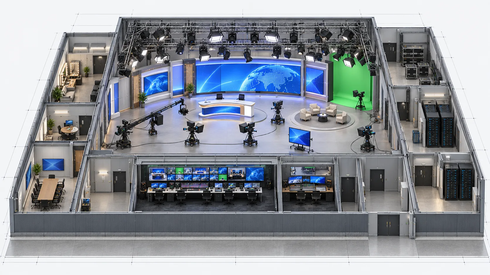
Concept visualisation of a TV studio with LED surfaces and cameras
Fig. 07.0 — TV studios
01Overview

Design for the camera view.

A backdrop needs to work in the recorded picture as well as in the room. Pixel pitch, camera distance, lens choice, exposure and studio light all shape the result. We agree the intended shots before choosing the LED system, then check the complete signal path with representative content.

Our scope covers LED surfaces, compatible processing, content connections, video routing, operator controls and interfaces with the existing studio. Cameras, lighting, audio, intercom, tally and programme production remain studio systems unless the agreed brief adds specific equipment. Camera tracking, real-time scene rendering and XR are separate scope.

Reference designs · equipment selection and site tests required. These configurations describe intended functions and example quantities. They are starting points for design, not completed installations or fixed equipment packages.

02Where it is used06 environments

Real environments, real priorities.

Who works in each kind of space, what they work with and what matters most to them.

Application register
No.EnvironmentWho uses itWork and contentWhat matters mostTypical systems
A01Presenter deskPresenter, camera operator and graphics operatorShow a still or moving backgroundClean framing and repeatable exposureST-01: one backdrop
A02Interview setPresenter, guests and camera crewAlternate between wide and close shotsLens, focus and moiré checks at each positionST-01: one backdrop
A03News setDirector, graphics and camera teamsPut different content behind the desk and on side surfacesThree independent images and coordinated presetsST-02: three surfaces
A04Sports analysis setPresenter and graphics operatorShow analysis beside the main backgroundReadable graphics and correct cropsST-02: three surfaces
A05Magazine programmeProduction and lighting teamsChange the visual identity between segmentsSaved image and brightness settings for approved scenesST-01 or ST-02
A06Continuity-sensitive studioTechnical director and LED operatorRecover the backdrop after specified signal failuresDefined failure coverage and measured recoveryST-03: primary and backup paths
03Typical configurations

Three starting points, compared.

Choose the workflow closest to your brief. Compare its scope, interfaces and operating limits before selecting equipment.

Compare all 3 configurations
Configuration

Single LED backdrop

ST-01

Match one background to the intended camera shots. Reference design · project selection and system tests required.

Explore ST-01

Three independent surfaces

ST-02

Operate three distinct images with coordinated formats and presets. Reference design · project selection and system tests required.

Explore ST-02

LED with defined failover

ST-03

Plan and test recovery from specified signal-path failures. Reference design · panel compatibility and recovery unverified.

Explore ST-03
Workflow

One background behind the presenter

Main backdrop and two separate images

One background with primary and backup signal paths

LED surfaces

1

3

1

Content sources

1 source, 1 video output

1 source, 3 independent video outputs

2 sources, 1 video output each

LED processors

1

3, one per surface

2 with a compatible failover platform

Distribution

Direct LED data paths

Separate LED data paths for each surface

2 compatible distribution units and paired cable paths

Synchronisation

Existing studio reference; new provision if required

Common reference for all three paths

Primary/backup reference provision, with its own failure tests

Monitoring

1 selectable video monitor and operator station

1 selectable video monitor and operator station

2 path monitors and operator station

Intended result

An approved camera view of the backdrop

Three correctly mapped, independently operated images

Documented recovery for the failures included in the design

Main limit

No automatic backup path

The shared content source remains a common failure point

Signal redundancy does not duplicate the LED panel electronics or guarantee uninterrupted pictures

Single LED backdrop

ST-01

Match one background to the intended camera shots. Reference design · project selection and system tests required.

Explore ST-01
Workflow
One background behind the presenter
LED surfaces
1
Content sources
1 source, 1 video output
LED processors
1
Distribution
Direct LED data paths
Synchronisation
Existing studio reference; new provision if required
Monitoring
1 selectable video monitor and operator station
Intended result
An approved camera view of the backdrop
Main limit
No automatic backup path

Three independent surfaces

ST-02

Operate three distinct images with coordinated formats and presets. Reference design · project selection and system tests required.

Explore ST-02
Workflow
Main backdrop and two separate images
LED surfaces
3
Content sources
1 source, 3 independent video outputs
LED processors
3, one per surface
Distribution
Separate LED data paths for each surface
Synchronisation
Common reference for all three paths
Monitoring
1 selectable video monitor and operator station
Intended result
Three correctly mapped, independently operated images
Main limit
The shared content source remains a common failure point

LED with defined failover

ST-03

Plan and test recovery from specified signal-path failures. Reference design · panel compatibility and recovery unverified.

Explore ST-03
Workflow
One background with primary and backup signal paths
LED surfaces
1
Content sources
2 sources, 1 video output each
LED processors
2 with a compatible failover platform
Distribution
2 compatible distribution units and paired cable paths
Synchronisation
Primary/backup reference provision, with its own failure tests
Monitoring
2 path monitors and operator station
Intended result
Documented recovery for the failures included in the design
Main limit
Signal redundancy does not duplicate the LED panel electronics or guarantee uninterrupted pictures

Reference configurations. Example quantities require project selection, compatibility checks and system acceptance tests.

Follow the signal path for your configuration.

ST-01

Single LED backdrop

Reference design · project selection and system tests required

A presenter or interview uses one LED background fed by one content source. The example has one processor, one video distribution amplifier, one selectable monitor, one control workstation and one management switch. Studio reference, working cameras, lighting and a camera return are supplied at agreed interfaces.

ST-01 · Single LED backdrop

One content feed reaches the backdrop; the operator checks both the feed and camera return.

Signal flow

Signal flow. Devices, connections and conditions follow the drawing.Open SVG ↗
ST-01 · Signal flowReference design. One video source, direct LED data, studio reference and separate management control with a camera return. Repeated device identifiers refer to the same equipment across views. Equipment illustrations are schematic; labels define quantities.{"sourceHash":"8fa5973d1931b3dc7146f2c59000963487f540d05228a3563bd0f3de3d2010df","view":"signal","nodes":["SRC","DA","PROC","LED","CAM","RETURN","MON"],"edges":["L01","L02","L03","L05","L06","L08"]}PIXEL COMMAND SOLUTIONS / ST-01 / SIGNAL FLOWSignal flowREFERENCE DESIGN · PROJECT VALIDATION REQUIREDSRC → DA: 1080p60 SDI1080p60 SDIDA → PROC: SDI output 1SDI output 1PROC → LED: 4 LED data chains 4 cabinets per chain4 LED data chainsCAM → RETURN: Existing studio video pathExisting studio videopathRETURN → MON: SDI camera return / input 2SDI camera return /input 2DA → MON: SDI output 2 / input 1SDI output 2 / input 1SRC · Content system ×1 SDI out + reference inSRCContent system ×1DA · 3G-SDI DA ×1 1 input / 2 outputsDA3G-SDI DA ×1PROC · LED processor ×1 One compatible receiver platformPROCLED processor ×1LED · One backdrop 16 cabinets / 16 included receivers 1920 × 1080 px exampleLEDOne backdropCAM · Studio camera ×1 Working lens and settingsCAMStudio camera ×1RETURN · Existing studio routing ×1 set One selected camera returnRETURNExisting studiorouting ×1 setMON · Video monitor ×1 2 selectable SDI inputsMONVideo monitor ×1Video / LED data
Devices, connections & design conditions 6 connections
  • One content feed reaches the backdrop; the operator checks both the feed and camera return.
  • ST-01 functional diagram showing SDI distribution, one LED processor, LED data, studio reference and separate management routes.
SRC
SRC · Content system ×1 SDI out + reference in
DA
DA · 3G-SDI DA ×1 1 input / 2 outputs
PROC
PROC · LED processor ×1 One compatible receiver platform
LED
LED · One backdrop 16 cabinets / 16 included receivers 1920 × 1080 px example
CAM
CAM · Studio camera ×1 Working lens and settings
RETURN
RETURN · Existing studio routing ×1 set One selected camera return
MON
MON · Video monitor ×1 2 selectable SDI inputs
  1. SRC → DA1080p60 SDI
  2. DA → PROCSDI output 1
  3. PROC → LED4 LED data chains 4 cabinets per chain
  4. CAM → RETURNExisting studio video path
  5. RETURN → MONSDI camera return / input 2
  6. DA → MONSDI output 2 / input 1

Control & status

Signal flow. Devices, connections and conditions follow the drawing.Open SVG ↗
ST-01 · Control & statusReference design. One video source, direct LED data, studio reference and separate management control with a camera return. Repeated device identifiers refer to the same equipment across views. Equipment illustrations are schematic; labels define quantities.{"sourceHash":"8fa5973d1931b3dc7146f2c59000963487f540d05228a3563bd0f3de3d2010df","view":"control","nodes":["SRC","PROC","PC","NET"],"edges":["L13","L14","L15"]}PIXEL COMMAND SOLUTIONS / ST-01 / CONTROL & STATUSControl & statusREFERENCE DESIGN · PROJECT VALIDATION REQUIREDPC ↔ NET: Ethernet commands / statusEthernet commands /statusNET ↔ SRC: Management EthernetManagement EthernetNET ↔ PROC: Management EthernetManagement EthernetSRC · Content system ×1 SDI out + reference inSRCContent system ×1PROC · LED processor ×1 One compatible receiver platformPROCLED processor ×1PC · Operator workstation ×1 Includes UI display; check camera returnPCOperator workstation×1NET · Management switch ×1 3 of at least 8 ports usedNETManagement switch ×1Control / status
Devices, connections & design conditions 3 connections
  • One content feed reaches the backdrop; the operator checks both the feed and camera return.
  • ST-01 functional diagram showing SDI distribution, one LED processor, LED data, studio reference and separate management routes.
SRC
SRC · Content system ×1 SDI out + reference in
PROC
PROC · LED processor ×1 One compatible receiver platform
PC
PC · Operator workstation ×1 Includes UI display; check camera return
NET
NET · Management switch ×1 3 of at least 8 ports used
  1. PC ↔ NETEthernet commands / status
  2. NET ↔ SRCManagement Ethernet
  3. NET ↔ PROCManagement Ethernet

Timing & camera check

Signal flow. Devices, connections and conditions follow the drawing.Open SVG ↗
ST-01 · Timing & camera checkReference design. One video source, direct LED data, studio reference and separate management control with a camera return. Repeated device identifiers refer to the same equipment across views. Equipment illustrations are schematic; labels define quantities.{"sourceHash":"8fa5973d1931b3dc7146f2c59000963487f540d05228a3563bd0f3de3d2010df","view":"reference","nodes":["SRC","PROC","LED","CAM","LIGHT","GEN","REFDA"],"edges":["L04","L07","L09","L10","L11","L12"]}PIXEL COMMAND SOLUTIONS / ST-01 / TIMING & CAMERA CHECKTiming & camera checkREFERENCE DESIGN · PROJECT VALIDATION REQUIREDLIGHT → CAM: Working light sceneWorking light sceneLED → CAM: Optical imageOptical imageGEN → REFDA: 75-ohm reference75-ohm referenceREFDA → SRC: Tri-level referenceTri-level referenceREFDA → PROC: Tri-level referenceTri-level referenceREFDA → CAM: Tri-level referenceTri-level referenceSRC · Content system ×1 SDI out + reference inSRCContent system ×1PROC · LED processor ×1 One compatible receiver platformPROCLED processor ×1LED · One backdrop 16 cabinets / 16 included receivers 1920 × 1080 px exampleLEDOne backdropCAM · Studio camera ×1 Working lens and settingsCAMStudio camera ×1LIGHT · Studio lighting ×1 setLIGHTStudio lighting ×1 setGEN · Existing reference ×1 interface Optional new generator replaces thisGENExisting reference ×1interfaceREFDA · Reference DA ×1 1 in / 4 out; 3 outputs usedREFDAReference DA ×1Optical / sceneTiming reference
Devices, connections & design conditions 6 connections
  • One content feed reaches the backdrop; the operator checks both the feed and camera return.
  • ST-01 functional diagram showing SDI distribution, one LED processor, LED data, studio reference and separate management routes.
SRC
SRC · Content system ×1 SDI out + reference in
PROC
PROC · LED processor ×1 One compatible receiver platform
LED
LED · One backdrop 16 cabinets / 16 included receivers 1920 × 1080 px example
CAM
CAM · Studio camera ×1 Working lens and settings
LIGHT
LIGHT · Studio lighting ×1 set
GEN
GEN · Existing reference ×1 interface Optional new generator replaces this
REFDA
REFDA · Reference DA ×1 1 in / 4 out; 3 outputs used
  1. LIGHT → CAMWorking light scene
  2. LED → CAMOptical image
  3. GEN → REFDA75-ohm reference
  4. REFDA → SRCTri-level reference
  5. REFDA → PROCTri-level reference
  6. REFDA → CAMTri-level reference

Typical architecture · not a project drawing

Workflow, boundaries and intended result

Operation

The source feeds the processor and the confidence monitor. The operator selects a saved display setup, checks the reference and input status, and compares the rendered background with the camera return under the approved light scene.

Boundary

A direct video path does not provide automatic recovery from source or processor failure. A supported frame store may be specified separately but is not a second live source. Camera timing adjustments available on another processing platform are not assumed for this configuration.

Intended result

One background with an agreed content map, display preset and recorded camera test for the intended shots.

Example equipment for ST-01

Example quantities for the selected configuration; final selection follows the approved design. A catalogue listing does not confirm stock, delivery time or complete-system compatibility.

LED surface assemblies with matched receivers
1

LED display equipment

LED processors
1

LED processing equipment

Compatible LED distribution units
Direct connection

Selected with the complete processing platform

Content systems / independent video outputs
1 / 1

Playback, output hardware and licences by design

Video distribution amplifiers
1

Interface and format checked against the signal schedule

Video monitors
1

At least 2 selectable inputs

Control workstation / management switch
1 / 1

Commands, status and local access by design

Reference infrastructure
Existing reference and 1 distribution unit

Counted once per selected studio design

Protected equipment power branches
1

Runtime and upstream separation by electrical design

Installation and service provision
1 studio set

Structure, LED power, cables, cooling and spares itemised for the site

ST-02

Three independent surfaces

Reference design · project selection and system tests required

A main backdrop and two side surfaces display different content. One source system provides three independent, synchronised video outputs. Each output has its own distribution amplifier, processor and LED surface. One operator station manages the three paths; a four-input monitor selects any of the three content feeds or the camera return.

ST-02 · Three independent surfaces

Three independent feeds reach three surfaces, with common reference and selectable monitoring.

Signal flow

Signal flow. Devices, connections and conditions follow the drawing.Open SVG ↗
ST-02 · Signal flowReference design with three independent SDI source outputs, three processors and LED surfaces, common reference and separate management. Repeated device identifiers refer to the same equipment across views. Equipment illustrations are schematic; labels define quantities.{"sourceHash":"ea1adb56e36daeee10a6f682f34bcad59013e143675452d6df2e84c7c8209388","view":"signal","nodes":["SRC","DA","PROC","MAIN","LEFT","RIGHT","CAM","RETURN","MON"],"edges":["L01","L02","L03","L04","L05","L07","L08","L12"]}PIXEL COMMAND SOLUTIONS / ST-02 / SIGNAL FLOWSignal flowREFERENCE DESIGN · PROJECT VALIDATION REQUIREDSRC → DA: SDI 1, 2, 3 / distinct content 3 physical links at 1080p60SDI 1, 2, 3 / distinctcontentDA → PROC: 3 separate SDI output-1 links3 separate SDI output-1linksPROC → MAIN: P1: 4 chains ×4 cabinetsP1: 4 chains ×4cabinetsPROC → LEFT: P2: 2 chains ×4 cabinetsP2: 2 chains ×4cabinetsPROC → RIGHT: P3: 2 chains ×4 cabinetsP3: 2 chains ×4cabinetsCAM → RETURN: Existing studio video pathsExisting studio videopathsRETURN → MON: SDI camera return / input 4SDI camera return /input 4DA → MON: 3 separate output-2 links Monitor inputs 1, 2, 33 separate output-2linksSRC · Content system ×1 3 independent SDI outputs One reference input locks all outputsSRCContent system ×1DA · 3G-SDI DAs ×3 One 1-to-2 DA per outputDA3G-SDI DAs ×3PROC · LED processors ×3 One per surface; matched receiversPROCLED processors ×3MAIN · Backdrop 16 cabinets / 16 included receivers 1920 × 1080 pxMAINBackdropLEFT · Surface 2 8 cabinets / 8 included receivers 960 × 1080 pxLEFTSurface 2RIGHT · Surface 3 8 cabinets / 8 included receivers 960 × 1080 pxRIGHTSurface 3CAM · Working cameras ×3CAMWorking cameras ×3RETURN · Existing studio routing ×1 set Select each camera for reviewRETURNExisting studiorouting ×1 setMON · Video monitor ×1 4 selectable SDI inputsMONVideo monitor ×1Video / LED data
Devices, connections & design conditions 8 connections
  • Three independent feeds reach three surfaces, with common reference and selectable monitoring.
  • ST-02 functional diagram showing three source outputs, three processors, separate LED surfaces and camera return monitoring.
SRC
SRC · Content system ×1 3 independent SDI outputs One reference input locks all outputs
DA
DA · 3G-SDI DAs ×3 One 1-to-2 DA per output
PROC
PROC · LED processors ×3 One per surface; matched receivers
MAIN
MAIN · Backdrop 16 cabinets / 16 included receivers 1920 × 1080 px
LEFT
LEFT · Surface 2 8 cabinets / 8 included receivers 960 × 1080 px
RIGHT
RIGHT · Surface 3 8 cabinets / 8 included receivers 960 × 1080 px
CAM
CAM · Working cameras ×3
RETURN
RETURN · Existing studio routing ×1 set Select each camera for review
MON
MON · Video monitor ×1 4 selectable SDI inputs
  1. SRC → DASDI 1, 2, 3 / distinct content 3 physical links at 1080p60
  2. DA → PROC3 separate SDI output-1 links
  3. PROC → MAINP1: 4 chains ×4 cabinets
  4. PROC → LEFTP2: 2 chains ×4 cabinets
  5. PROC → RIGHTP3: 2 chains ×4 cabinets
  6. CAM → RETURNExisting studio video paths
  7. RETURN → MONSDI camera return / input 4
  8. DA → MON3 separate output-2 links Monitor inputs 1, 2, 3

Control & status

Signal flow. Devices, connections and conditions follow the drawing.Open SVG ↗
ST-02 · Control & statusReference design with three independent SDI source outputs, three processors and LED surfaces, common reference and separate management. Repeated device identifiers refer to the same equipment across views. Equipment illustrations are schematic; labels define quantities.{"sourceHash":"ea1adb56e36daeee10a6f682f34bcad59013e143675452d6df2e84c7c8209388","view":"control","nodes":["SRC","PROC","PC","NET"],"edges":["L17","L18","L19"]}PIXEL COMMAND SOLUTIONS / ST-02 / CONTROL & STATUSControl & statusREFERENCE DESIGN · PROJECT VALIDATION REQUIREDPC ↔ NET: Ethernet commands / statusEthernet commands /statusNET ↔ SRC: 1 management link1 management linkNET ↔ PROC: 3 management links3 management linksSRC · Content system ×1 3 independent SDI outputs One reference input locks all outputsSRCContent system ×1PROC · LED processors ×3 One per surface; matched receiversPROCLED processors ×3PC · Operator workstation ×1 Includes UI displayPCOperator workstation×1NET · Management switch ×1 5 of at least 8 ports usedNETManagement switch ×1Control / status
Devices, connections & design conditions 3 connections
  • Three independent feeds reach three surfaces, with common reference and selectable monitoring.
  • ST-02 functional diagram showing three source outputs, three processors, separate LED surfaces and camera return monitoring.
SRC
SRC · Content system ×1 3 independent SDI outputs One reference input locks all outputs
PROC
PROC · LED processors ×3 One per surface; matched receivers
PC
PC · Operator workstation ×1 Includes UI display
NET
NET · Management switch ×1 5 of at least 8 ports used
  1. PC ↔ NETEthernet commands / status
  2. NET ↔ SRC1 management link
  3. NET ↔ PROC3 management links

Timing & camera check

Signal flow. Devices, connections and conditions follow the drawing.Open SVG ↗
ST-02 · Timing & camera checkReference design with three independent SDI source outputs, three processors and LED surfaces, common reference and separate management. Repeated device identifiers refer to the same equipment across views. Equipment illustrations are schematic; labels define quantities.{"sourceHash":"ea1adb56e36daeee10a6f682f34bcad59013e143675452d6df2e84c7c8209388","view":"reference","nodes":["SRC","PROC","MAIN","LEFT","RIGHT","CAM","LIGHT","GEN","REFDA"],"edges":["L06","L09","L10","L11","L13","L14","L15","L16"]}PIXEL COMMAND SOLUTIONS / ST-02 / TIMING & CAMERA CHECKTiming & camera checkREFERENCE DESIGN · PROJECT VALIDATION REQUIREDLIGHT → CAM: Working light sceneWorking light sceneMAIN → CAM: Optical imageOptical imageLEFT → CAM: Optical imageOptical imageRIGHT → CAM: Optical imageOptical imageGEN → REFDA: 75-ohm reference75-ohm referenceREFDA → SRC: 1 reference link1 reference linkREFDA → PROC: 3 reference links3 reference linksREFDA → CAM: 3 reference links3 reference linksSRC · Content system ×1 3 independent SDI outputs One reference input locks all outputsSRCContent system ×1PROC · LED processors ×3 One per surface; matched receiversPROCLED processors ×3MAIN · Backdrop 16 cabinets / 16 included receivers 1920 × 1080 pxMAINBackdropLEFT · Surface 2 8 cabinets / 8 included receivers 960 × 1080 pxLEFTSurface 2RIGHT · Surface 3 8 cabinets / 8 included receivers 960 × 1080 pxRIGHTSurface 3CAM · Working cameras ×3CAMWorking cameras ×3LIGHT · Studio light ×1 setLIGHTStudio light ×1 setGEN · Existing reference ×1 interfaceGENExisting reference ×1interfaceREFDA · Reference DA ×1 1 in / 8 out; 7 outputs usedREFDAReference DA ×1Optical / sceneTiming reference
Devices, connections & design conditions 8 connections
  • Three independent feeds reach three surfaces, with common reference and selectable monitoring.
  • ST-02 functional diagram showing three source outputs, three processors, separate LED surfaces and camera return monitoring.
SRC
SRC · Content system ×1 3 independent SDI outputs One reference input locks all outputs
PROC
PROC · LED processors ×3 One per surface; matched receivers
MAIN
MAIN · Backdrop 16 cabinets / 16 included receivers 1920 × 1080 px
LEFT
LEFT · Surface 2 8 cabinets / 8 included receivers 960 × 1080 px
RIGHT
RIGHT · Surface 3 8 cabinets / 8 included receivers 960 × 1080 px
CAM
CAM · Working cameras ×3
LIGHT
LIGHT · Studio light ×1 set
GEN
GEN · Existing reference ×1 interface
REFDA
REFDA · Reference DA ×1 1 in / 8 out; 7 outputs used
  1. LIGHT → CAMWorking light scene
  2. MAIN → CAMOptical image
  3. LEFT → CAMOptical image
  4. RIGHT → CAMOptical image
  5. GEN → REFDA75-ohm reference
  6. REFDA → SRC1 reference link
  7. REFDA → PROC3 reference links
  8. REFDA → CAM3 reference links

Typical architecture · not a project drawing

Workflow, boundaries and intended result

Operation

The content team receives three pixel maps. Presets define crops, brightness and operating states for each surface. The studio reference reaches the source, all processors and camera system through a designed distribution path.

Boundary

An output splitter repeats one picture; it cannot create the three required pictures. This baseline uses independent surfaces, not a seamless panoramic canvas. It has no backup media server or redundant processor set. A failure of the shared source can affect all three surfaces.

Intended result

Three images that can be checked and operated separately, with camera tests covering shots that contain more than one surface.

Example equipment for ST-02

Example quantities for the selected configuration; final selection follows the approved design. A catalogue listing does not confirm stock, delivery time or complete-system compatibility.

LED surface assemblies with matched receivers
3

LED display equipment

LED processors
3

LED processing equipment

Compatible LED distribution units
Direct connection

Selected with the complete processing platform

Content systems / independent video outputs
1 / 3

Playback, output hardware and licences by design

Video distribution amplifiers
3

Interface and format checked against the signal schedule

Video monitors
1

At least 4 selectable inputs

Control workstation / management switch
1 / 1

Commands, status and local access by design

Reference infrastructure
Existing reference and 1 distribution unit

Counted once per selected studio design

Protected equipment power branches
1

Runtime and upstream separation by electrical design

Installation and service provision
1 studio set

Structure, LED power, cables, cooling and spares itemised for the site

ST-03

LED with defined failover

Reference design · panel compatibility and recovery unverified

One backdrop needs recovery from agreed signal-path failures. Two independent content sources feed two processors. Two compatible distribution units connect paired paths to the same LED receiver chains. The design also calls for primary/backup reference generation, reference changeover and separately protected equipment power branches.

ST-03 · LED with defined failover

Two processors share a compatible pair of distribution units, with paired paths to the receiver chains.

Signal flow

Signal flow. Devices, connections and conditions follow the drawing.Open SVG ↗
ST-03 · Signal flowConditional reference topology. Two sources and processors connect to a matched pair of distribution units through four direct trunks. Eight paired receiver chains serve one LED surface. Complete-chain compatibility and recovery tests remain required. Repeated device identifiers refer to the same equipment across views. Equipment illustrations are schematic; labels define quantities.{"sourceHash":"418a7ffa03f1be1553b07f70317386c1092205a6ed94701d0d36759c05604cb2","view":"signal","nodes":["SA","SB","DA","DB","PA","PB","XA","XB","LED","MA","MB","CAM","RETURN"],"edges":["L01","L02","L03","L04","L05","L06","L07","L08","L09","L10","L12","L13","L14","L15","L16"]}PIXEL COMMAND SOLUTIONS / ST-03 / SIGNAL FLOWSignal flowREFERENCE DESIGN · PROJECT VALIDATION REQUIREDSA → DA: 1080p60 SDI1080p60SDISB → DB: 1080p60 SDI1080p60SDIDA → PA: SDI output 1SDIoutput 1DB → PB: SDI output 1SDIoutput 1PA → XA: Trunk A to X1 · 10GA → X1 ·10GPA → XB: Trunk B to X1 · 10GB → X1 · 10GPB → XA: Trunk A to X2 · 10GA → X2 · 10GPB → XB: Trunk B to X2 · 10GB → X2 ·10GXA → LED: Ports 1-8 to chain starts Platform LED dataPorts 1–8 · chainstartsXB → LED: Matching ports 1-8 to chain ends Platform LED dataPorts 1–8 · chain endsCAM → RETURN: Existing studio video pathsStudiovideoRETURN → MA: SDI return A / input 2SDI return A · input 2RETURN → MB: SDI return B / input 2SDI return B · input 2DA → MA: SDI output 2 / input 1SDI out 2 · input 1DB → MB: SDI output 2 / input 1SDI out 2 · input 1SRC-A · Content system ×1SASRC-A · Content system×1SRC-B · Content system ×1SBSRC-B · Content system×1DA-A · SDI DA ×1 1 in / 2 outDADA-A · SDI DA ×1DA-B · SDI DA ×1 1 in / 2 outDBDA-B · SDI DA ×1PROC-A · Processor ×1 Primary role; trunk A + BPAPROC-A · Processor ×1PROC-B · Processor ×1 Backup role; trunk A + BPBPROC-B · Processor ×1DIST-A · Matched distribution ×1 Inputs X1 / X2; outputs 1-8XADIST-A · Matcheddistribution ×1DIST-B · Matched distribution ×1 Inputs X1 / X2; outputs 1-8XBDIST-B · Matcheddistribution ×1LED · One backdrop 16 cabinets / 16 included receivers 8 paired chains of 2 cabinets 1920 × 1080 px exampleLEDOne backdropMON-A · Video monitor ×1 2 selectable SDI inputsMAMON-A · Video monitor×1MON-B · Video monitor ×1 2 selectable SDI inputsMBMON-B · Video monitor×1CAM · Studio cameras ×2CAMStudio cameras ×2RETURN · Existing studio routing ×1 set 2 camera returnsRETURNExisting studiorouting ×1 setVideo / LED data
Devices, connections & design conditions 15 connections
  • Two processors share a compatible pair of distribution units, with paired paths to the receiver chains.
  • ST-03 reference diagram showing two content sources, two processors, distribution inputs X1 and X2, paired LED paths and separate reference and control connections.
SA
SRC-A · Content system ×1
SB
SRC-B · Content system ×1
DA
DA-A · SDI DA ×1 1 in / 2 out
DB
DA-B · SDI DA ×1 1 in / 2 out
PA
PROC-A · Processor ×1 Primary role; trunk A + B
PB
PROC-B · Processor ×1 Backup role; trunk A + B
XA
DIST-A · Matched distribution ×1 Inputs X1 / X2; outputs 1-8
XB
DIST-B · Matched distribution ×1 Inputs X1 / X2; outputs 1-8
LED
LED · One backdrop 16 cabinets / 16 included receivers 8 paired chains of 2 cabinets 1920 × 1080 px example
MA
MON-A · Video monitor ×1 2 selectable SDI inputs
MB
MON-B · Video monitor ×1 2 selectable SDI inputs
CAM
CAM · Studio cameras ×2
RETURN
RETURN · Existing studio routing ×1 set 2 camera returns
  1. SA → DA1080p60 SDI
  2. SB → DB1080p60 SDI
  3. DA → PASDI output 1
  4. DB → PBSDI output 1
  5. PA → XATrunk A to X1 · 10G
  6. PA → XBTrunk B to X1 · 10G
  7. PB → XATrunk A to X2 · 10G
  8. PB → XBTrunk B to X2 · 10G
  9. XA → LEDPorts 1-8 to chain starts Platform LED data
  10. XB → LEDMatching ports 1-8 to chain ends Platform LED data
  11. CAM → RETURNExisting studio video paths
  12. RETURN → MASDI return A / input 2
  13. RETURN → MBSDI return B / input 2
  14. DA → MASDI output 2 / input 1
  15. DB → MBSDI output 2 / input 1

Control & status

Signal flow. Devices, connections and conditions follow the drawing.Open SVG ↗
ST-03 · Control & statusConditional reference topology. Two sources and processors connect to a matched pair of distribution units through four direct trunks. Eight paired receiver chains serve one LED surface. Complete-chain compatibility and recovery tests remain required. Repeated device identifiers refer to the same equipment across views. Equipment illustrations are schematic; labels define quantities.{"sourceHash":"418a7ffa03f1be1553b07f70317386c1092205a6ed94701d0d36759c05604cb2","view":"control","nodes":["SA","SB","PA","PB","PC","NET"],"edges":["L25","L26","L27","L28","L29"]}PIXEL COMMAND SOLUTIONS / ST-03 / CONTROL & STATUSControl & statusREFERENCE DESIGN · PROJECT VALIDATION REQUIREDPC ↔ NET: Ethernet commands / statusEthernet commands /statusNET ↔ SA: ManagementManagementNET ↔ SB: ManagementManagementNET ↔ PA: Input / lock / active-path statusInput / lock /active-path statusNET ↔ PB: Input / lock / active-path statusInput / lock /active-path statusSRC-A · Content system ×1SASRC-A · Content system×1SRC-B · Content system ×1SBSRC-B · Content system×1PROC-A · Processor ×1 Primary role; trunk A + BPAPROC-A · Processor ×1PROC-B · Processor ×1 Backup role; trunk A + BPBPROC-B · Processor ×1PC · Operator workstation ×1 Includes UI display; commands + feedbackPCOperator workstation×1NET · Management switch ×1 5 of at least 8 ports usedNETManagement switch ×1Control / status
Devices, connections & design conditions 5 connections
  • Two processors share a compatible pair of distribution units, with paired paths to the receiver chains.
  • ST-03 reference diagram showing two content sources, two processors, distribution inputs X1 and X2, paired LED paths and separate reference and control connections.
SA
SRC-A · Content system ×1
SB
SRC-B · Content system ×1
PA
PROC-A · Processor ×1 Primary role; trunk A + B
PB
PROC-B · Processor ×1 Backup role; trunk A + B
PC
PC · Operator workstation ×1 Includes UI display; commands + feedback
NET
NET · Management switch ×1 5 of at least 8 ports used
  1. PC ↔ NETEthernet commands / status
  2. NET ↔ SAManagement
  3. NET ↔ SBManagement
  4. NET ↔ PAInput / lock / active-path status
  5. NET ↔ PBInput / lock / active-path status

Timing & camera check

Signal flow. Devices, connections and conditions follow the drawing.Open SVG ↗
ST-03 · Timing & camera checkConditional reference topology. Two sources and processors connect to a matched pair of distribution units through four direct trunks. Eight paired receiver chains serve one LED surface. Complete-chain compatibility and recovery tests remain required. Repeated device identifiers refer to the same equipment across views. Equipment illustrations are schematic; labels define quantities.{"sourceHash":"418a7ffa03f1be1553b07f70317386c1092205a6ed94701d0d36759c05604cb2","view":"reference","nodes":["SA","SB","PA","PB","LED","CAM","LIGHT","GEN","CHANGE","REFDA"],"edges":["L11","L17","L18","L19","L20","L21","L22","L23","L24"]}PIXEL COMMAND SOLUTIONS / ST-03 / TIMING & CAMERA CHECKTiming & camera checkREFERENCE DESIGN · PROJECT VALIDATION REQUIREDLIGHT → CAM: Working light sceneWorking light sceneLED → CAM: Optical imageOptical imageGEN → CHANGE: 2 reference lines2 reference linesCHANGE → REFDA: 2 reference lines2 reference linesREFDA → SA: A-group refA-group refREFDA → SB: B-group refB-group refREFDA → PA: A-group refA-group refREFDA → PB: B-group refB-group refREFDA → CAM: 2 camera ref lines2 camera ref linesSRC-A · Content system ×1SASRC-A · Content system×1SRC-B · Content system ×1SBSRC-B · Content system×1PROC-A · Processor ×1 Primary role; trunk A + BPAPROC-A · Processor ×1PROC-B · Processor ×1 Backup role; trunk A + BPBPROC-B · Processor ×1LED · One backdrop 16 cabinets / 16 included receivers 8 paired chains of 2 cabinets 1920 × 1080 px exampleLEDOne backdropCAM · Studio cameras ×2CAMStudio cameras ×2LIGHT · Studio lighting ×1 setLIGHTStudio lighting ×1 setGEN · Reference generators ×2 Primary / backup; compatible timingGENReference generators×2CHANGE · Reference changeover ×1 2 in / 2 isolated identical outCHANGEReference changeover×1REFDA · Reference DAs ×2 Each 1 in / 4 out; 3 outputs usedREFDAReference DAs ×2Optical / sceneTiming reference
Devices, connections & design conditions 9 connections
  • Two processors share a compatible pair of distribution units, with paired paths to the receiver chains.
  • ST-03 reference diagram showing two content sources, two processors, distribution inputs X1 and X2, paired LED paths and separate reference and control connections.
SA
SRC-A · Content system ×1
SB
SRC-B · Content system ×1
PA
PROC-A · Processor ×1 Primary role; trunk A + B
PB
PROC-B · Processor ×1 Backup role; trunk A + B
LED
LED · One backdrop 16 cabinets / 16 included receivers 8 paired chains of 2 cabinets 1920 × 1080 px example
CAM
CAM · Studio cameras ×2
LIGHT
LIGHT · Studio lighting ×1 set
GEN
GEN · Reference generators ×2 Primary / backup; compatible timing
CHANGE
CHANGE · Reference changeover ×1 2 in / 2 isolated identical out
REFDA
REFDA · Reference DAs ×2 Each 1 in / 4 out; 3 outputs used
  1. LIGHT → CAMWorking light scene
  2. LED → CAMOptical image
  3. GEN → CHANGE2 reference lines
  4. CHANGE → REFDA2 reference lines
  5. REFDA → SAA-group ref
  6. REFDA → SBB-group ref
  7. REFDA → PAA-group ref
  8. REFDA → PBB-group ref
  9. REFDA → CAM2 camera ref lines

Typical architecture · not a project drawing

Workflow, boundaries and intended result

Operation

Each path has a confidence feed. The operator can verify the backup content, request a controlled transfer and see the resulting active-path status. Source content, pixel mapping and image settings must be maintained on both paths. A valid video signal carrying a frozen application image needs an operator or separately specified content-health check.

Boundary

A supported processor transfer can interrupt the picture. Cable-path recovery and processor recovery are different tests. Receiver cards, LED modules, cabinet power supplies, reference distribution and common upstream utilities retain failure exposure unless separately engineered. No seamless switching or blanket availability figure is implied.

Intended result

An agreed list of covered failures, measured recovery records and an operator procedure for transfer, restoration and maintenance.

Example equipment for ST-03

Example quantities for the selected configuration; final selection follows the approved design. A catalogue listing does not confirm stock, delivery time or complete-system compatibility.

LED surface assemblies with matched receivers
1

LED display equipment

LED processors
2

LED processing equipment

Compatible LED distribution units
2

Selected with the complete processing platform

Content systems / independent video outputs
2 / 2

Playback, output hardware and licences by design

Video distribution amplifiers
2

Interface and format checked against the signal schedule

Video monitors
2

At least 2 selectable inputs per monitor

Control workstation / management switch
1 / 1

Commands, status and local access by design

Reference infrastructure
2 generators, 1 changeover and 2 distribution units

Counted once per selected studio design

Protected equipment power branches
2

Runtime and upstream separation by electrical design

Installation and service provision
1 studio set

Structure, LED power, cables, cooling and spares itemised for the site

05Reference architectureInteractive

How a typical system fits together.

Four layers, from the sources to the people operating the system. Select a layer to see its components and the interfaces between them.

Typical architecture · TV studios

L2 · Selected layerProcessing & transport

How signals are routed and processed in a typical system of this kind.

Components and interfaces
  • LED processorsSDI / HDMIReceivers, distribution and processors are selected as one compatible system
  • Video distributionSDI / HDMIReceivers, distribution and processors are selected as one compatible system
  • Platform-specific LED dataSDI / HDMIReceivers, distribution and processors are selected as one compatible system
Documented scope · TV studios
  • LED surfaces and their compatible receiver and processing platform.
  • Content formats, pixel maps and source connections.
  • Video distribution, synchronisation and operator monitoring.
  • Image adjustment with the studio camera and lighting teams.
  • Failure recovery where specified for ST-03.
  • Commissioning records, saved settings and operator training.
Prepare for the first conversation
  1. 01Studio plan, proposed surfaces and maintenance access.
  2. 02Camera models, lenses, positions, focus distances and shot examples.
  3. 03Frame rates, shutter settings, exposure and reference arrangements.
  4. 04Lighting scenes and intended LED brightness range.
  5. 05Content examples, pixel maps and required independent feeds.
  6. 06Existing video interfaces, cable routes and production return points.
  7. 07Required failure coverage, allowable interruption and recovery workflow.
  8. 08Equipment ownership, power, cooling, structure, budget and programme.
Share your studio brief
06Design parametersTypical guidance · confirmed per project

What the design has to get right.

The engineering checks behind every drawing. Rules of thumb are starting points; the project values are confirmed with the people named.

Design parameters
No.ParameterGuidanceRule of thumbConfirmed with
D01Camera positionsRecord the closest, widest and most detailed shotsTest the proposed LED at the real lens and focus settingsDirector of photography
D02Pixel mapDefine each surface in pixels and cabinetsCheck total canvas and every loaded data portLED and content teams
D03Video formatFix resolution, exact frame rate, sampling, range and bit depthVerify every source, distribution and processor interfaceStudio engineer
D04TimingAgree reference type, exposure and phase adjustmentTest actual lock and camera output at every approved modeCamera and LED engineers
D05Colour and lightAgree working brightness, white point and light scenesReview faces, dark gradients and highlights through the cameraLighting and camera teams
D06ContentSupply stills, motion, fine detail and titlesCheck crops and avoid content that reveals unwanted sampling patternsGraphics team
D07Failure recoveryName the failures that must be coveredDefine allowed interruption before the ST-03 testsTechnical director
D08InstallationCheck service access, noise, heat, power and support loadsIssue equipment data to the responsible site designersFacilities and structural teams
Common mistakes

And how the design process prevents them.

  1. M01

    Mistake: Selecting LED by refresh-rate marketing alone

    Prevention: Evaluate the panel, receiver settings and camera exposure together

  2. M02

    Mistake: Treating three connectors as three independent images

    Prevention: Demonstrate simultaneous, distinct content on all three outputs

  3. M03

    Mistake: Mixing a processor with unverified receiver cards

    Prevention: Obtain a complete platform and firmware compatibility schedule

  4. M04

    Mistake: Assuming genlock removes moiré

    Prevention: Check lens, distance, focus, aperture, content and pixel pitch in the intended shots

  5. M05

    Mistake: Calling two ports a redundant system

    Prevention: Trace the supported alternate route and test each claimed failure

  6. M06

    Mistake: Monitoring only the source

    Prevention: Include a camera return and inspection of the displayed LED image

07Design referencesEditions checked per project

The references we design to.

Equipment documentation, industry guides and project requirements inform the design. Confirm applicable editions and acceptance criteria for the site.

Equipment documentation and industry guides04

  • Approved studio format scheduleProject design referenceResolution, frame rate, SDI mapping or HDMI profile The project schedule defines the actual modesCheck current edition
  • Processor and receiver documentationProject design referencePort loading, timing, firmware and redundancy wiring Features must apply to the selected hardware and releaseCheck current edition
  • Camera and lens operating documentationProject design referenceReference input, exposure and permitted operating settings Camera models and lenses are recorded in the test sheetCheck current edition
  • Project electrical and structural documentsProject design referenceCircuits, service access, cooling and mounting Equipment data needs approval by the responsible designersCheck current edition
08Integrations07 interfaces

Connected to the building and its IT.

The systems this solution usually exchanges signals or data with, and why. Each interface is agreed with the system owner.

  • I01

    Graphics and playback

    Agreed SDI or HDMI outputs; content files

    Provide the correct canvas and timing for each surface

  • I02

    Studio reference

    Terminated reference connections through distribution

    Align sources, display processing and cameras where supported

  • I03

    Camera system

    Optical LED image; existing SDI camera return

    Judge the result in the recorded picture

  • I04

    Lighting

    Agreed light scenes and operating levels

    Repeat the conditions used in image acceptance

  • I05

    Production control

    Approved video feed and return points

    Define the LED interface to the existing studio workflow

  • I06

    Operator network

    Management Ethernet and supported device controls

    Select presets and inspect actual input, lock and path status

  • I07

    Facilities

    Power, cooling, mounting and service access

    Keep the installation maintainable and within the site design

09Delivery

From the brief to an accepted system.

The six stages follow the selected configuration. Platform development or unconfirmed software functions require their own agreed scope and validation milestones.

Our services
  1. Stage 01

    Scope and architecture

    Shot and content brief; LED/studio responsibility boundary; selected configuration and failure objectives

    • Camera and content brief
    • LED/studio scope boundary
    • Agreed failure objectives
  2. Stage 02

    Design and approval

    Surface and pixel maps; video/reference/control diagrams; mounting, power and cooling requirements

    • Surface and pixel maps
    • Video, reference and control paths
    • Power and mounting requirements
  3. Stage 03

    Selection and supply

    Agreed equipment and licence schedule; complete-platform compatibility record; service and spare-parts schedule

    • Agreed equipment schedule
    • Platform compatibility record
    • Licences and spare-parts list
  4. Stage 04

    Installation and programming

    Installed and labelled paths; saved image and operating presets; configured status and reference interfaces

    • Installed and labelled paths
    • Image and operating presets
    • Reference and status setup
  5. Stage 05

    Commissioning and tests

    Recorded camera tests; format, crop and timing checks; ST-03 recovery measurements where specified

    • Recorded camera tests
    • Format and timing checks
    • Specified recovery tests
  6. Stage 06

    Handover

    Operator training; as-built maps and configuration backups; test reports and recovery instructions

    • Operator training
    • Maps and settings backups
    • Test and recovery guides
Documented outcomes
01

Match one background to the intended camera shots.

02

Operate three distinct images with coordinated formats and presets.

03

Plan and test recovery from specified signal-path failures.

10Acceptance

Verify the complete workflow.

Agree the demonstration and the records before accepting the selected configuration.

ST-01

Reference design · project selection and system tests required

Before testing, agree the cameras, lenses, frame rates, shutter settings, shot positions, LED brightness, lighting scenes and representative content. Record the versions and receiver configuration. Review dark tones, gradients, motion and fine detail in both wide and close shots; agree the acceptable image with the camera team. ST-01 checks one complete content-to-camera path. ST-02 adds simultaneous distinct images, preset recall and shots spanning the three surfaces. ST-03 adds the agreed source, processor, cable, distribution and reference failures, with time-stamped observations of interruption, recovery and operator status. Uncovered failures are recorded alongside covered ones. The handover includes pixel maps, content profiles, signal and port schedules, calibrated settings, software versions, test clips and an operating guide. A camera or firmware change can require part of the acceptance programme to be repeated.

Record supplied: Agreed criteria, equipment and version schedule, measured test results and recovery procedure.

These are planned project checks. The reference configuration has not passed physical system acceptance.
ST-02

Reference design · project selection and system tests required

Before testing, agree the cameras, lenses, frame rates, shutter settings, shot positions, LED brightness, lighting scenes and representative content. Record the versions and receiver configuration. Review dark tones, gradients, motion and fine detail in both wide and close shots; agree the acceptable image with the camera team. ST-01 checks one complete content-to-camera path. ST-02 adds simultaneous distinct images, preset recall and shots spanning the three surfaces. ST-03 adds the agreed source, processor, cable, distribution and reference failures, with time-stamped observations of interruption, recovery and operator status. Uncovered failures are recorded alongside covered ones. The handover includes pixel maps, content profiles, signal and port schedules, calibrated settings, software versions, test clips and an operating guide. A camera or firmware change can require part of the acceptance programme to be repeated.

Record supplied: Agreed criteria, equipment and version schedule, measured test results and recovery procedure.

These are planned project checks. The reference configuration has not passed physical system acceptance.

ST-03

Reference design · panel compatibility and recovery unverified

Before testing, agree the cameras, lenses, frame rates, shutter settings, shot positions, LED brightness, lighting scenes and representative content. Record the versions and receiver configuration. Review dark tones, gradients, motion and fine detail in both wide and close shots; agree the acceptable image with the camera team. ST-01 checks one complete content-to-camera path. ST-02 adds simultaneous distinct images, preset recall and shots spanning the three surfaces. ST-03 adds the agreed source, processor, cable, distribution and reference failures, with time-stamped observations of interruption, recovery and operator status. Uncovered failures are recorded alongside covered ones. The handover includes pixel maps, content profiles, signal and port schedules, calibrated settings, software versions, test clips and an operating guide. A camera or firmware change can require part of the acceptance programme to be repeated.

Record supplied: Agreed criteria, equipment and version schedule, measured test results and recovery procedure.

These are planned project checks. The reference configuration has not passed physical system acceptance.

11Inputs and FAQ

Before we begin.

What to send us, and practical answers before the project starts.

Does a high LED refresh rate guarantee a clean camera image?

No. The result also depends on the receiver configuration, exposure, scan behaviour, brightness and camera settings. We evaluate the complete combination with the intended shots.

Will genlock remove moiré?

Genlock addresses timing. Moiré also depends on how the LED pixel pattern is sampled by the camera and lens. Distance, framing, focus, aperture and content need a separate camera test.

Can three surfaces show different content?

Yes, ST-02 is designed around three independent source outputs and three processing paths. The content maps and available output hardware are checked before selection.

Can we reuse our LED cabinets?

Possibly. We need the exact cabinet, receiver card, driver and firmware details, plus access to representative panels. Changing the processor alone does not establish platform compatibility.

Is ST-03 seamless or fully redundant?

ST-03 defines recovery for agreed failures. Processor transfer can interrupt the picture, and signal redundancy does not protect every panel or utility component. Coverage and permitted interruption are agreed before testing.

Are cameras, lighting and a broadcast control room included?

The baseline integrates the LED signal path with your studio interfaces. Camera supply, production switching, audio, intercom, lighting systems and control-room construction need their own agreed scope.

Is this an XR or virtual-production system?

The configurations cover studio backgrounds and display integration. Camera tracking, rendered perspective, real-time scene engines and XR workflows are separate designs.

What happens when a source freezes but still outputs video?

A signal-loss detector may not recognise that fault. ST-03 includes operator monitoring; automated content-health detection must be separately specified and tested if required.

12Talk to us

Share your studio brief.

Send studio plans, camera modes, content examples and your required failure coverage.