Sheet 08 — LED & LCD video walls
Solution 08 · LED & LCD video walls

A bigger picture, planned down to the pixel.

Bring your content onto a readable, consistent display surface. We plan the screen, processing, structure, power and service access together, from a lobby LED wall to a tiled LCD display with separate source windows.

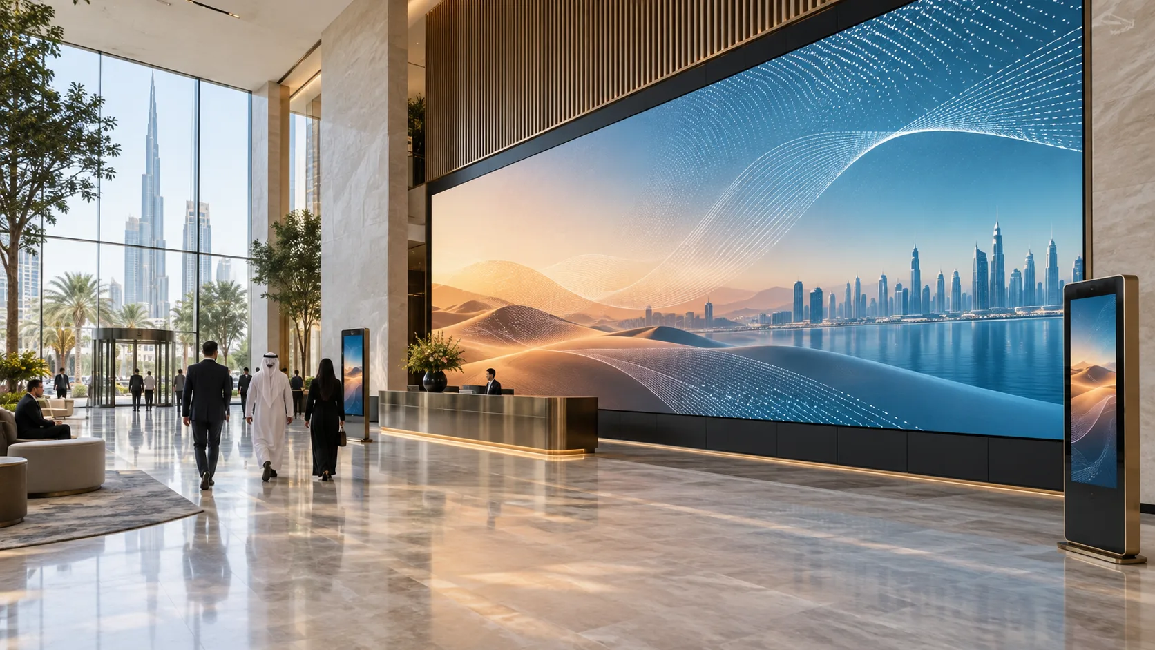
Concept visualisation of a fine-pitch LED wall integrated into a contemporary Dubai lobby
Fig. 08.0 — LED & LCD video walls
01Overview

Start with the content and the people viewing it.

A welcome film, a presentation and a detailed dashboard place different demands on a wall. The closest viewer helps determine pixel pitch; the farthest viewer and the smallest important detail help determine image size. We review both before selecting the display technology.

The physical surface and the system that composes the image are separate decisions. LED cabinets determine size and native resolution; their sending controller maps video to the receiving electronics. An LCD wall has visible seams and needs an output for each panel. A compositor adds source windows and layouts when the brief requires them.

These three reference configurations describe intended functions and example quantities. They are starting points for project design, not fixed purchase packages or completed installations. Component compatibility and complete-system performance still require project verification.

Intended outcomes: content sized for its viewers; a surface that can be serviced; documented source routes and operating settings.

For operator roles, KVM and shared operational workflows, see Control rooms & command centres. For publishing and scheduling across screens, see Digital signage & retail displays. Sound, conferencing and teaching workflows are developed under Meeting & conference rooms and Learning & presentation spaces.

Stage use needs a separate live-production and mounting brief. Studio use needs tests with the actual cameras, shutter settings, working light and content. These indoor reference walls do not establish suitability for outdoor, touring or camera-critical use.

For camera-critical LED, see TV studios. For stage sound, lighting and guest production, see Concert & event venues.

02Where it is used06 environments

Real environments, real priorities.

Who works in each kind of space, what they work with and what matters most to them.

Application register
No.EnvironmentWho uses itWork and contentWhat matters mostTypical systems
A01Interior lobbyVisitors and reception staffWelcome films and brand contentContent geometry, ambient light and daily operationVW-01 with one content source
A02Briefing or presentation spacePresenters and guestsSlides, demonstrations and source changesReadable text and a defined guest connectionVW-02 with two selectable sources
A03Large brand zoneVisitors and content teamA larger continuous imageExact cabinet grid, distribution and service accessVW-02 with a prepared canvas
A04Information roomStaff and supervisorsTwo information sources in saved layoutsWindow sizes and clear separation from panel seamsVW-03 with a compositor
A05Meeting or teaching roomParticipants and presentersShared material on a large surfaceViewing positions and the room AV interfaceA wall subsystem within the room design
A06Retail or exhibition interiorVisitors and content managersPromotions and directoriesLight levels, content production and approved schedulesA wall with separately specified content management
03Typical configurations

Three starting points, compared.

Choose the workflow closest to your brief. Compare its scope, interfaces and operating limits before selecting equipment.

Compare all 3 configurations
Configuration

Compact LED wall

VW-01

Show one prepared source on a 2.56 × 1.44 m LED surface. Reference design; receiver compatibility and power data pending.

Explore VW-01

Large LED wall

VW-02

Fill a 5.12 × 2.88 m LED surface and select between two agreed sources. Reference design; receiver compatibility and power data pending.

Explore VW-02

LCD wall with source windows

VW-03

Place two captured sources in saved layouts across four LCD panels. Reference design; final panel and compositor build pending.

Explore VW-03
Intended use

Welcome or presentation content from one source

Larger brand or presentation surface with source selection

Two information sources in saved layouts

Display surface

4 × 3 indoor LED cabinets

8 × 6 indoor LED cabinets

2 × 2 landscape FHD LCD panels

Example size

2.56 × 1.44 m

5.12 × 2.88 m

Four 55-inch panels; final envelope follows panel dimensions and installation gaps

Native pixels

1376 × 774; 1,065,024 pixels

2752 × 1548; 4,260,096 pixels

3840 × 2160 across four panels; visible seams remain

Sources in the base example

One content PC

One content PC and one client presentation device

Two client PCs through two capture inputs

Processing

One combined scaler and LED sending controller

One combined scaler and larger LED sending controller

One compositor with capture, four display outputs and layout software

Display connections

Four LED data runs, one per cabinet column

Eight LED data runs, one per cabinet column

Four separate HDMI outputs, one per panel

Everyday operation

Local content operation and brightness adjustment

Select either source and recall approved settings

Recall and adjust approved two-source layouts

Service provision

Front service and a project-specific spare-parts plan

Front service and a project-specific spare-parts plan

Four service mounts and a proposed spare panel

Base boundary

One full-surface source; content scheduling is separate

One selected full-surface source; additional simultaneous windows require design

Two captured sources; IP decoding, KVM and resilience are separate

Delivery status

Reference design; receiver compatibility and power data pending

Reference design; receiver compatibility and power data pending

Reference design; final panel and compositor build pending
Compact LED wall

VW-01

Show one prepared source on a 2.56 × 1.44 m LED surface. Reference design; receiver compatibility and power data pending.

Explore VW-01
Intended use
Welcome or presentation content from one source
Display surface
4 × 3 indoor LED cabinets
Example size
2.56 × 1.44 m
Native pixels
1376 × 774; 1,065,024 pixels
Sources in the base example
One content PC
Processing
One combined scaler and LED sending controller
Display connections
Four LED data runs, one per cabinet column
Everyday operation
Local content operation and brightness adjustment
Service provision
Front service and a project-specific spare-parts plan
Base boundary
One full-surface source; content scheduling is separate
Delivery status
Reference design; receiver compatibility and power data pending

Large LED wall

VW-02

Fill a 5.12 × 2.88 m LED surface and select between two agreed sources. Reference design; receiver compatibility and power data pending.

Explore VW-02
Intended use
Larger brand or presentation surface with source selection
Display surface
8 × 6 indoor LED cabinets
Example size
5.12 × 2.88 m
Native pixels
2752 × 1548; 4,260,096 pixels
Sources in the base example
One content PC and one client presentation device
Processing
One combined scaler and larger LED sending controller
Display connections
Eight LED data runs, one per cabinet column
Everyday operation
Select either source and recall approved settings
Service provision
Front service and a project-specific spare-parts plan
Base boundary
One selected full-surface source; additional simultaneous windows require design
Delivery status
Reference design; receiver compatibility and power data pending

LCD wall with source windows

VW-03

Place two captured sources in saved layouts across four LCD panels. Reference design; final panel and compositor build pending.

Explore VW-03
Intended use
Two information sources in saved layouts
Display surface
2 × 2 landscape FHD LCD panels
Example size
Four 55-inch panels; final envelope follows panel dimensions and installation gaps
Native pixels
3840 × 2160 across four panels; visible seams remain
Sources in the base example
Two client PCs through two capture inputs
Processing
One compositor with capture, four display outputs and layout software
Display connections
Four separate HDMI outputs, one per panel
Everyday operation
Recall and adjust approved two-source layouts
Service provision
Four service mounts and a proposed spare panel
Base boundary
Two captured sources; IP decoding, KVM and resilience are separate
Delivery status
Reference design; final panel and compositor build pending
Reference configurations. Example quantities require project selection, compatibility checks and system acceptance tests. The LCD pixel total is the sum of four panel rasters. Bezel compensation changes image mapping and may hide content at the seams; it does not add physical pixels.

Follow the signal path for your configuration.

VW-01

Compact LED wall

Reference design; receiver compatibility and power data pending

One content PC presents a prepared welcome film, brand image or presentation on a compact indoor wall.

VW-01 · Reference drawing

VW-01 · Cabinet map

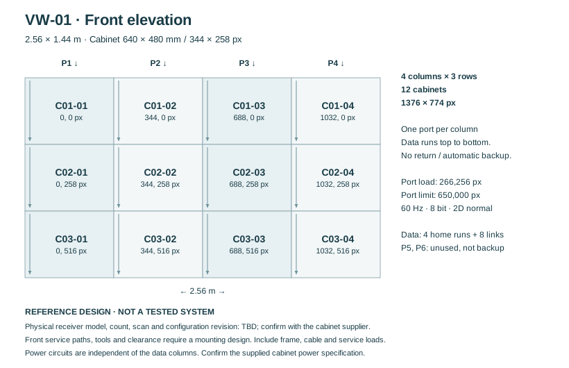
Front-view example: four columns, three cabinets per column.

Reference design; receiver compatibility and power data pending

VW-01 · Cabinet map

Pixel map · authored engineering elevationOpen SVG ↗
Typical 4 by 3 LED cabinet elevation with port numbers, logical receiver groups and canvas dimensions.
Text description of VW-01 · Cabinet map
  • Front-view example: four columns, three cabinets per column.
  • Typical 4 by 3 LED cabinet elevation with port numbers, logical receiver groups and canvas dimensions.

Typical architecture · not a project drawing

VW-01 · Reference drawing

VW-01 · Compact LED wall

One source, one combined LED controller and four cabinet-column data routes.

Reference design; receiver compatibility and power data pending

Signal flow

Signal flow. Devices, connections and conditions follow the drawing.Open SVG ↗
VW-01 · Signal flow Repeated device identifiers refer to the same equipment across views. Equipment illustrations are schematic; labels define quantities.{"sourceHash":"ae2d51fb5140a5e885a675a8b4904b221df534abd769df443e885aaafe372c4e","view":"signal","nodes":["source","controller","wall"],"edges":["L01","L02"]}PIXEL COMMAND SOLUTIONS / VW-01 / SIGNAL FLOWSignal flowREFERENCE DESIGN · PROJECT VALIDATION REQUIREDsource → controller: HDMIHDMIcontroller → wall: LED DATA × 4LED DATA × 4Content PC × 1 HDMI 1920 × 1080p60 Prepared wall canvassourceContent PC × 1Combined LED controller × 1 Scaler + sender; one selected source 4 loaded outputs; 60 Hz / 8 bit No automatic backup in baselinecontrollerCombined LEDcontroller × 1LED surface × 12 cabinets 4 × 3 · 2.56 × 1.44 m 1376 × 774 canvas 4 logical column chains 12 included receiver / PSU sets Physical card model / count TBDwallLED surface × 12cabinetsVideo / LED data
Devices, connections & design conditions 2 connections
  • One source, one combined LED controller and four cabinet-column data routes.
  • Reference VW-01 flow showing HDMI, four LED data routes, separate IP control and supported status feedback, and power distribution.
source
Content PC × 1 HDMI 1920 × 1080p60 Prepared wall canvas
controller
Combined LED controller × 1 Scaler + sender; one selected source 4 loaded outputs; 60 Hz / 8 bit No automatic backup in baseline
wall
LED surface × 12 cabinets 4 × 3 · 2.56 × 1.44 m 1376 × 774 canvas 4 logical column chains 12 included receiver / PSU sets Physical card model / count TBD
  1. source → controllerHDMI
  2. controller → wallLED DATA × 4

Control & power

Signal flow. Devices, connections and conditions follow the drawing.Open SVG ↗
VW-01 · Control & power Repeated device identifiers refer to the same equipment across views. Equipment illustrations are schematic; labels define quantities.{"sourceHash":"ae2d51fb5140a5e885a675a8b4904b221df534abd769df443e885aaafe372c4e","view":"control","nodes":["controller","wall","service","network","power"],"edges":["L03","L04","L05","L06","L07"]}PIXEL COMMAND SOLUTIONS / VW-01 / CONTROL & POWERControl & powerREFERENCE DESIGN · PROJECT VALIDATION REQUIREDwall → controller: Supported receiver status; verify supplied assemblySupported receiverstatusservice ↔ network: IPIPnetwork ↔ controller: Control / statusControl / statuspower → wall: Display mainsDisplay mainspower → controller: Rack mainsRack mainsCombined LED controller × 1 Scaler + sender; one selected source 4 loaded outputs; 60 Hz / 8 bit No automatic backup in baselinecontrollerCombined LEDcontroller × 1LED surface × 12 cabinets 4 × 3 · 2.56 × 1.44 m 1376 × 774 canvas 4 logical column chains 12 included receiver / PSU sets Physical card model / count TBDwallLED surface × 12cabinetsSupport laptop × 1 Setup and supported status Local authorised accessserviceSupport laptop × 1Control LAN switch × 1 INF: shared infrastructure LED DATA bypasses this switchnetworkControl LAN switch × 1Power distribution × 1 set Protected supply: display + rack Cabinet power / circuits TBDpowerPower distribution × 1setControl / statusPower
Devices, connections & design conditions 5 connections
  • One source, one combined LED controller and four cabinet-column data routes.
  • Reference VW-01 flow showing HDMI, four LED data routes, separate IP control and supported status feedback, and power distribution.
controller
Combined LED controller × 1 Scaler + sender; one selected source 4 loaded outputs; 60 Hz / 8 bit No automatic backup in baseline
wall
LED surface × 12 cabinets 4 × 3 · 2.56 × 1.44 m 1376 × 774 canvas 4 logical column chains 12 included receiver / PSU sets Physical card model / count TBD
service
Support laptop × 1 Setup and supported status Local authorised access
network
Control LAN switch × 1 INF: shared infrastructure LED DATA bypasses this switch
power
Power distribution × 1 set Protected supply: display + rack Cabinet power / circuits TBD
  1. wall → controllerSupported receiver status; verify supplied assembly
  2. service ↔ networkIP
  3. network ↔ controllerControl / status
  4. power → wallDisplay mains
  5. power → controllerRack mains

Typical architecture · not a project drawing

Workflow, boundaries and intended result

Composition

Twelve LED cabinets with their receiving electronics and power supplies, one combined scaler/sending controller, one content PC and one support laptop. Four data home runs feed the four columns; eight inter-cabinet links continue those chains. A mounting assembly, site installation infrastructure and a matched-spares plan complete the example.

Content path

The wall canvas is 1376 × 774. A standard HDMI source timing carries the prepared canvas, with agreed crop or scaling settings. Native canvas size and HDMI transport resolution are documented separately.

Boundaries

The base example uses one full-surface source. It does not include a multi-source compositor, CMS, ambient-light sensor, sound system or backup signal path. LED power demand remains subject to the selected cabinet specification. The proposed receiver arrangement must be confirmed with the cabinet supplier.

Intended result

Staff can start the agreed content, set the approved brightness and restore the documented configuration after maintenance.

Example equipment for VW-01

Example quantities for the selected configuration; final selection follows the approved design. A catalogue listing does not confirm stock, delivery time or complete-system compatibility.

LED cabinets, including receivers and power supplies
12

LED displays and controllers

Combined LED scaler/sending controller
1

LED displays and controllers

Content PC supplied / client source PCs
1 / 0

Agree source ownership and HDMI format

Support laptop or control workstation
1

LED setup or LCD layout client

LED data home runs / inter-cabinet links
4 / 8

Cabinet-specific connections and cable lengths

HDMI input / output cable assemblies
1 / 0

Validate the full cable route at the selected timing

Surface support assembly
1

Structural and service-access design

Shared installation infrastructure
1 allocation

Control switch, rack, power distribution and installation cabling, counted once per selected wall

Planned service spares
Matched LED parts; quantities agreed

Confirm supply revision and storage arrangements

VW-02

Large LED wall

Reference design; receiver compatibility and power data pending

A larger indoor brand or presentation surface switches between a content PC and a client presentation device.

VW-02 · Reference drawing

VW-02 · Cabinet map

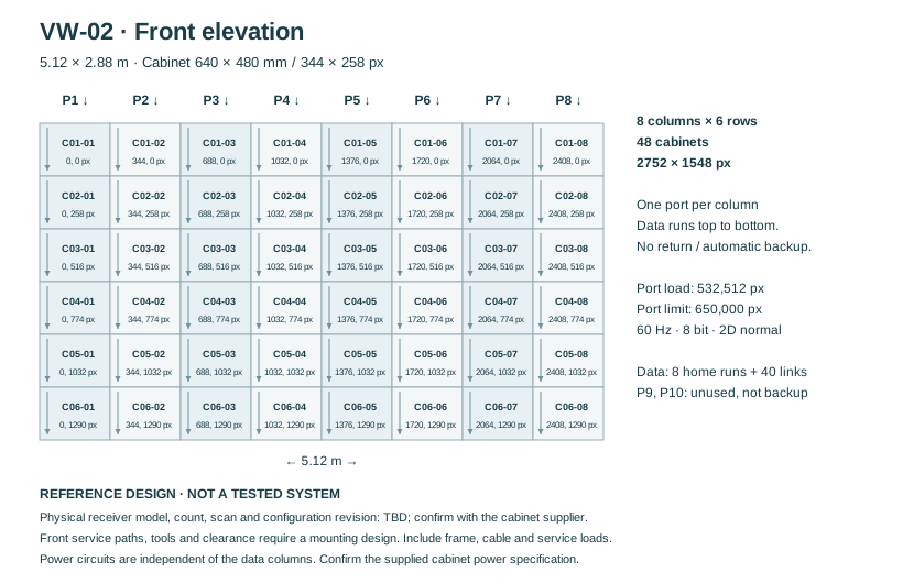
Front-view example: eight columns, six cabinets per column.

Reference design; receiver compatibility and power data pending

VW-02 · Cabinet map

Pixel map · authored engineering elevationOpen SVG ↗
Typical 8 by 6 LED cabinet elevation with port numbers, logical receiver groups and canvas dimensions.
Text description of VW-02 · Cabinet map
  • Front-view example: eight columns, six cabinets per column.
  • Typical 8 by 6 LED cabinet elevation with port numbers, logical receiver groups and canvas dimensions.

Typical architecture · not a project drawing

VW-02 · Reference drawing

VW-02 · Large LED wall

Two selectable sources and eight separately checked LED outputs.

Reference design; receiver compatibility and power data pending

Signal flow

Signal flow. Devices, connections and conditions follow the drawing.Open SVG ↗
VW-02 · Signal flow Repeated device identifiers refer to the same equipment across views. Equipment illustrations are schematic; labels define quantities.{"sourceHash":"02c2e1c82db6c7442c5ede922cf073ea2dafa41c791f02c4bf708965def6ba25","view":"signal","nodes":["source","client","controller","wall"],"edges":["L01","L02","L03"]}PIXEL COMMAND SOLUTIONS / VW-02 / SIGNAL FLOWSignal flowREFERENCE DESIGN · PROJECT VALIDATION REQUIREDsource → controller: HDMIHDMIclient → controller: HDMIHDMIcontroller → wall: LED DATA × 8LED DATA × 8Content PC × 1 HDMI 3840 × 2160p60 Prepared wall canvassourceContent PC × 1Client source × 1 HDMI 1920 × 1080p60clientClient source × 1Combined LED controller × 1 Scaler + sender; one selected source 8 loaded outputs; 60 Hz / 8 bit No automatic backup in baselinecontrollerCombined LEDcontroller × 1LED surface × 48 cabinets 8 × 6 · 5.12 × 2.88 m 2752 × 1548 canvas 8 logical column chains 48 included receiver / PSU sets Physical card model / count TBDwallLED surface × 48cabinetsVideo / LED data
Devices, connections & design conditions 3 connections
  • Two selectable sources and eight separately checked LED outputs.
  • Reference VW-02 flow showing two HDMI inputs, a combined LED controller, eight column data routes, control feedback and power.
source
Content PC × 1 HDMI 3840 × 2160p60 Prepared wall canvas
client
Client source × 1 HDMI 1920 × 1080p60
controller
Combined LED controller × 1 Scaler + sender; one selected source 8 loaded outputs; 60 Hz / 8 bit No automatic backup in baseline
wall
LED surface × 48 cabinets 8 × 6 · 5.12 × 2.88 m 2752 × 1548 canvas 8 logical column chains 48 included receiver / PSU sets Physical card model / count TBD
  1. source → controllerHDMI
  2. client → controllerHDMI
  3. controller → wallLED DATA × 8

Control & power

Signal flow. Devices, connections and conditions follow the drawing.Open SVG ↗
VW-02 · Control & power Repeated device identifiers refer to the same equipment across views. Equipment illustrations are schematic; labels define quantities.{"sourceHash":"02c2e1c82db6c7442c5ede922cf073ea2dafa41c791f02c4bf708965def6ba25","view":"control","nodes":["controller","wall","service","network","power"],"edges":["L04","L05","L06","L07","L08"]}PIXEL COMMAND SOLUTIONS / VW-02 / CONTROL & POWERControl & powerREFERENCE DESIGN · PROJECT VALIDATION REQUIREDwall → controller: Supported receiver status; verify supplied assemblySupported receiverstatusservice ↔ network: IPIPnetwork ↔ controller: Control / statusControl / statuspower → wall: Display mainsDisplay mainspower → controller: Rack mainsRack mainsCombined LED controller × 1 Scaler + sender; one selected source 8 loaded outputs; 60 Hz / 8 bit No automatic backup in baselinecontrollerCombined LEDcontroller × 1LED surface × 48 cabinets 8 × 6 · 5.12 × 2.88 m 2752 × 1548 canvas 8 logical column chains 48 included receiver / PSU sets Physical card model / count TBDwallLED surface × 48cabinetsSupport laptop × 1 Setup and supported status Local authorised accessserviceSupport laptop × 1Control LAN switch × 1 INF: shared infrastructure LED DATA bypasses this switchnetworkControl LAN switch × 1Power distribution × 1 set Protected supply: display + rack Cabinet power / circuits TBDpowerPower distribution × 1setControl / statusPower
Devices, connections & design conditions 5 connections
  • Two selectable sources and eight separately checked LED outputs.
  • Reference VW-02 flow showing two HDMI inputs, a combined LED controller, eight column data routes, control feedback and power.
controller
Combined LED controller × 1 Scaler + sender; one selected source 8 loaded outputs; 60 Hz / 8 bit No automatic backup in baseline
wall
LED surface × 48 cabinets 8 × 6 · 5.12 × 2.88 m 2752 × 1548 canvas 8 logical column chains 48 included receiver / PSU sets Physical card model / count TBD
service
Support laptop × 1 Setup and supported status Local authorised access
network
Control LAN switch × 1 INF: shared infrastructure LED DATA bypasses this switch
power
Power distribution × 1 set Protected supply: display + rack Cabinet power / circuits TBD
  1. wall → controllerSupported receiver status; verify supplied assembly
  2. service ↔ networkIP
  3. network ↔ controllerControl / status
  4. power → wallDisplay mains
  5. power → controllerRack mains

Typical architecture · not a project drawing

Workflow, boundaries and intended result

Composition

Forty-eight LED cabinets with receiving electronics and power supplies, one combined scaler/sending controller, one content PC, one client source and one support laptop. Eight data home runs feed eight cabinet columns, with forty inter-cabinet links. Mounting, site infrastructure and a matched-spares plan follow the larger load and service area.

Content path

The content PC uses a 3840 × 2160 HDMI transport with an agreed crop for the 2752 × 1548 wall canvas. The second source uses a tested presentation timing and scales to the wall. The base workflow selects one source at a time.

Boundaries

This canvas exceeds a 3.9-million-pixel controller. The example requires a larger controller and a separate check of all eight loaded outputs. Spare outputs do not provide complete wall redundancy. Additional source windows, fibre links, camera synchronisation and a resilient signal chain are separately designed options.

Intended result

The approved content fills the larger surface with a documented pixel and port map, and staff can change between the two agreed sources.

Example equipment for VW-02

Example quantities for the selected configuration; final selection follows the approved design. A catalogue listing does not confirm stock, delivery time or complete-system compatibility.

LED cabinets, including receivers and power supplies
48

LED displays and controllers

Combined LED scaler/sending controller
1, sized for the larger canvas

LED displays and controllers

Content PC supplied / client source PCs
1 / 1

Agree source ownership and HDMI format

Support laptop or control workstation
1

LED setup or LCD layout client

LED data home runs / inter-cabinet links
8 / 40

Cabinet-specific connections and cable lengths

HDMI input / output cable assemblies
2 / 0

Validate the full cable route at the selected timing

Surface support assembly
1

Structural and service-access design

Shared installation infrastructure
1 allocation

Control switch, rack, power distribution and installation cabling, counted once per selected wall

Planned service spares
Matched LED parts; quantities agreed

Confirm supply revision and storage arrangements

VW-03

LCD wall with source windows

Reference design; final panel and compositor build pending
Two client PCs provide information that staff place in saved layouts on a four-panel wall.

VW-03 · LCD wall with source windows

A compositor captures two sources and drives each of four panels.

Signal flow

Signal flow. Devices, connections and conditions follow the drawing.Open SVG ↗
VW-03 · Signal flow Repeated device identifiers refer to the same equipment across views. Equipment illustrations are schematic; labels define quantities.{"sourceHash":"1743750c97d159c8b19b4ea5f27c66cfed401635eaeb7299aa120b9d536fbd92","view":"signal","nodes":["sources","compositor","d1","d2","d3","d4"],"edges":["L01","L02","L03","L04","L05"]}PIXEL COMMAND SOLUTIONS / VW-03 / SIGNAL FLOWSignal flowREFERENCE DESIGN · PROJECT VALIDATION REQUIREDsources → compositor: HDMI × 2HDMI × 2compositor → d1: OUT1OUT1compositor → d2: OUT2OUT2compositor → d3: OUT3OUT3compositor → d4: OUT4OUT4Client sources × 2 A → capture IN1 B → capture IN2 HDMI 1920 × 1080p60 eachsourcesClient sources × 2Compositor build × 1 Chassis + capture card × 1 Four-output graphics card × 1 Layout licence set × 1 Two sources in agreed layoutscompositorCompositor build × 1D1 · OUT1 1920 × 1080p60d1D1 · OUT1D2 · OUT2 1920 × 1080p60d2D2 · OUT2D3 · OUT3 1920 × 1080p60d3D3 · OUT3D4 · OUT4 1920 × 1080p60d4D4 · OUT4Video / LED data
Devices, connections & design conditions 5 connections
  • A compositor captures two sources and drives each of four panels.
  • Reference VW-03 flow showing two HDMI capture inputs, four HDMI panel outputs, layout control, panel status and power.
sources
Client sources × 2 A → capture IN1 B → capture IN2 HDMI 1920 × 1080p60 each
compositor
Compositor build × 1 Chassis + capture card × 1 Four-output graphics card × 1 Layout licence set × 1 Two sources in agreed layouts
d1
D1 · OUT1 1920 × 1080p60
d2
D2 · OUT2 1920 × 1080p60
d3
D3 · OUT3 1920 × 1080p60
d4
D4 · OUT4 1920 × 1080p60
  1. sources → compositorHDMI × 2
  2. compositor → d1OUT1
  3. compositor → d2OUT2
  4. compositor → d3OUT3
  5. compositor → d4OUT4

Control & power

Signal flow. Devices, connections and conditions follow the drawing.Open SVG ↗
VW-03 · Control & power Repeated device identifiers refer to the same equipment across views. Equipment illustrations are schematic; labels define quantities.{"sourceHash":"1743750c97d159c8b19b4ea5f27c66cfed401635eaeb7299aa120b9d536fbd92","view":"control","nodes":["compositor","d3","d4","control","network","power"],"edges":["L06","L07","L08","L09","L10"]}PIXEL COMMAND SOLUTIONS / VW-03 / CONTROL & POWERControl & powerREFERENCE DESIGN · PROJECT VALIDATION REQUIREDcontrol ↔ network: IPIPnetwork ↔ compositor: Layouts / statusLayouts / statusnetwork ↔ d3: Panel IP / status × 4Panel IP / status × 4power → d4: Panel mains × 4Panel mains × 4power → compositor: Rack mainsRack mainsCompositor build × 1 Chassis + capture card × 1 Four-output graphics card × 1 Layout licence set × 1 Two sources in agreed layoutscompositorCompositor build × 1D3 · OUT3 1920 × 1080p60d3D3 · OUT3D4 · OUT4 1920 × 1080p60d4D4 · OUT4Layout workstation × 1 Recall / adjust saved layouts Separate from the source PCscontrolLayout workstation × 1Control LAN switch × 1 Client + compositor + 4 panels Supported status; not KVMnetworkControl LAN switch × 1Power distribution × 1 set Panels + compositor + controls MEP circuit design requiredpowerPower distribution × 1setControl / statusPower
Devices, connections & design conditions 5 connections
  • A compositor captures two sources and drives each of four panels.
  • Reference VW-03 flow showing two HDMI capture inputs, four HDMI panel outputs, layout control, panel status and power.
compositor
Compositor build × 1 Chassis + capture card × 1 Four-output graphics card × 1 Layout licence set × 1 Two sources in agreed layouts
d3
D3 · OUT3 1920 × 1080p60
d4
D4 · OUT4 1920 × 1080p60
control
Layout workstation × 1 Recall / adjust saved layouts Separate from the source PCs
network
Control LAN switch × 1 Client + compositor + 4 panels Supported status; not KVM
power
Power distribution × 1 set Panels + compositor + controls MEP circuit design required
  1. control ↔ networkIP
  2. network ↔ compositorLayouts / status
  3. network ↔ d3Panel IP / status × 4
  4. power → d4Panel mains × 4
  5. power → compositorRack mains

Typical architecture · not a project drawing

Workflow, boundaries and intended result

Composition

Four identical FHD LCD panels, four service mounts, one compositor chassis with one capture card and one four-output graphics card, one layout-software licence set and one control workstation. Two HDMI input cables connect the client sources; four HDMI output cables connect the panels. Site infrastructure and one proposed matching spare panel are scheduled separately.

Content path

Each source is captured at the agreed 1920 × 1080/60 timing. Four independent 1920 × 1080/60 outputs form the 2 × 2 desktop. Layouts can show the two sources together or enlarge a selected source, with important text kept clear of the seams.

Boundaries

Four display outputs do not imply four captured sources or a particular IP-stream capacity. The chassis, cards, drivers and software licences must be specified as one compatible build. KVM, alarm workflows, IP decoding, remote access and failover are separate requirements. A spare panel is a service provision, not automatic recovery.

Intended result

Staff can recall the approved layouts, see both sources and identify a missing input or disconnected panel through the agreed checks and supported diagnostics.

Example equipment for VW-03

Example quantities for the selected configuration; final selection follows the approved design. A catalogue listing does not confirm stock, delivery time or complete-system compatibility.

LCD video-wall panels / service mounts
4 / 4

Specify matching panels and mounting interfaces

Compositor chassis / capture card / four-output card
1 / 1 / 1

Video wall processors; confirm exact input, output and software functions

Layout software licence set
1

Confirm licence features and supported system build

Content PC supplied / client source PCs
0 / 2

Agree source ownership and HDMI format

Support laptop or control workstation
1

LED setup or LCD layout client

HDMI input / output cable assemblies
2 / 4

Validate the full cable route at the selected timing

Surface support assembly
1 plus four mounts

Structural and service-access design

Shared installation infrastructure
1 allocation

Control switch, rack, power distribution and installation cabling, counted once per selected wall

Planned service spares
1 matching spare panel proposed

Confirm supply revision and storage arrangements

05Reference architectureInteractive

How a typical system fits together.

Four layers, from the sources to the people operating the system. Select a layer to see its components and the interfaces between them.

Typical architecture · LED & LCD video walls

L2 · Selected layerProcessing & transport

How signals are routed and processed in a typical system of this kind.

Components and interfaces
  • Combined scaler/sending controllerHDMIVW-01/02; LED output sockets do not connect through the control-network switch
  • Dedicated LED data linksHDMIVW-01/02; LED output sockets do not connect through the control-network switch
  • Capture, compositor software and four HDMI display outputsHDMIVW-03; output count, input count and decoding capacity are separate checks
Documented scope · LED & LCD video walls
  • LED or LCD surface, with a documented pixel map.
  • Source connections, scaling and the required composition functions.
  • Data routes, controls and supported status reporting.
  • Mounting, power and cooling coordination, with service access.
  • Calibration, acceptance checks, settings and maintenance documentation.
Prepare for the first conversation
  1. 01Available wall width, height, location and a plan or photograph.
  2. 02Nearest and farthest viewing positions, smallest important text and example content.
  3. 03Day and evening lighting, including windows and direct sunlight.
  4. 04Source list, connection formats, protected content and simultaneous-window needs.
  5. 05Building structure information, finishes and available front or rear service space.
  6. 06Power, cooling, rack position and estimated signal-route lengths.
  7. 07Daily operating hours, failure tolerance and required recovery workflow.
  8. 08Content owner, IT interfaces, maintenance arrangements and budget priorities.
Share your video wall brief
06Design parametersTypical guidance · confirmed per project

What the design has to get right.

The engineering checks behind every drawing. Rules of thumb are starting points; the project values are confirmed with the people named.

Design parameters
No.ParameterGuidanceRule of thumbConfirmed with
D01ReadabilityReview the smallest important text from the farthest viewing position.Use real content and an agreed image-size method; pitch alone cannot establish readability.Users and content owner
D02LED pitch and geometryCheck close viewing and the exact cabinet raster.Calculate from pixels per cabinet; a rounded model name is not a geometry input.Display supplier and AV designer
D03LCD envelope and seamsPlan panel bodies, installation gaps and clearance together.Do not turn bezel compensation into extra physical pixels or a gap-free image.Panel supplier and fit-out team
D04Processing capacityCount inputs, simultaneous windows and every loaded output.Check the selected frame rate, bit depth, topology and receiver configuration.Processor supplier and integrator
D05Source timingKeep content canvas, HDMI timing and panel outputs distinct.Save the approved EDID, crop, scale and output settings.Content and IT teams
D06Ambient lightReview brightness and reflections at the actual wall position.Test day and evening scenes; indoor examples do not establish direct-sun suitability.Client and lighting designer
D07Mounting and massAdd cabinets or panels, frame, cables and service loads.A display-only mass is not a structural design load.Structural engineer
D08Power and coolingObtain maximum input, normal operation, inrush and heat data.Size the complete installation from the supplied equipment; unknown data stays unknown.Supplier and MEP engineer
D09Service and sparesDemonstrate access to a module or panel.Match spare revision and calibration records; document the replacement procedure.Facilities team and supplier
D10AvailabilityIdentify what happens when an input, cable or controller fails.Specify the failure coverage and test it; unused ports and cold spares are not automatic redundancy.Client and integrator
Common mistakes

And how the design process prevents them.

  1. M01

    Mistake: Selecting a controller only from total pixels

    Prevention: Check every output and the actual receiver topology at the operating mode.

  2. M02

    Mistake: Calling any four-output device a multi-source compositor

    Prevention: Specify independent inputs, simultaneous windows, software and licences.

  3. M03

    Mistake: Publishing cabinet mass as the wall's total load

    Prevention: Add support, cabling and service loads through the structural design.

  4. M04

    Mistake: Guessing power from brightness or surface area

    Prevention: Obtain the power specification for the exact supplied cabinet.

  5. M05

    Mistake: Placing key text across LCD seams

    Prevention: Review the final window layouts and bezel compensation with real content.

  6. M06

    Mistake: Assuming a refresh-rate figure guarantees camera performance

    Prevention: Test the actual camera, shutter, working light and screen together.

07Design referencesEditions checked per project

The references we design to.

Equipment documentation, industry guides and project requirements inform the design. Confirm applicable editions and acceptance criteria for the site.

Equipment documentation and industry guides04

  • ANSI/AVIXA V202.01Display Image Size for 2D Content in Audiovisual SystemsReadability and image sizingCheck current edition
  • AVIXA V201.01Image System Contrast RatioContrast under the agreed room lightingCheck current edition
  • ANSI/AVIXA D402.02Audiovisual Systems Performance VerificationAgree tests and retain their resultsCheck current edition
  • AVIXA F502.02Rack Design for AV SystemsProcessor rack planning and documentationCheck current edition
08Integrations08 interfaces

Connected to the building and its IT.

The systems this solution usually exchanges signals or data with, and why. Each interface is agreed with the system owner.

  • I01

    Content production

    Canvas, safe-area and timing specification

    Deliver assets that match the wall and avoid LCD seams.

  • I02

    Client IT and sources

    HDMI, EDID and management IP

    Confirm device ownership, output timing and permitted support access.

  • I03

    Building structure

    Load schedule and mounting drawings

    Approve the support and fixings for the complete installation.

  • I04

    Fit-out and joinery

    Elevation, section and service-clearance drawings

    Keep ventilation and removal paths accessible after finishes are installed.

  • I05

    MEP services

    Circuit, inrush and heat schedules

    Design power distribution and cooling for the selected equipment.

  • I06

    Lighting and shades

    Agreed room scenes

    Check reflections and suitable display brightness in normal use.

  • I07

    Signage CMS

    Content-player interface; optional

    Scheduling and publication belong to the selected CMS, not the LED receiver.

  • I08

    Room controls or BMS

    Documented IP or serial interface; optional

    Agree commands, actual status, permissions and loss-of-connection behaviour.

09Equipment01 catalogue types

What a system of this kind is built from.

The catalogue types this solution usually draws on. Makes and models are selected per project, against the confirmed specification.

Open the catalogue
10Delivery

From the brief to an accepted system.

The six stages follow the selected configuration. Platform development or unconfirmed software functions require their own agreed scope and validation milestones.

Our services
  1. Stage 01

    Scope and architecture

    Viewing and content brief; LED/LCD comparison; source, operation and service boundaries.

    • Viewing and content brief
    • LED or LCD comparison
    • Source and service boundaries
  2. Stage 02

    Design and approval

    Dimensioned elevation and section; pixel, port and input/output maps; structure, power and cooling requirements.

    • Surface and pixel layout
    • Input and output maps
    • Structure, power and cooling data
  3. Stage 03

    Selection and supply

    Agreed equipment and licence schedule; confirmed controller/receiver or compositor build; compatible spare-parts schedule.

    • Agreed display and processing set
    • Checked interface compatibility
    • Matched spare-parts schedule
  4. Stage 04

    Installation and programming

    Installed and labelled display system; configured source mapping and controls; saved calibration and operating settings.

    • Installed and labelled wall
    • Configured image mapping
    • Saved brightness and colour settings
  5. Stage 05

    Commissioning and tests

    Real-content readability and uniformity checks; input and output tests; service demonstration and agreed recovery tests.

    • Real-content and uniformity checks
    • Source and output test records
    • Service and recovery checks
  6. Stage 06

    Handover

    As-built drawings and configuration files; test records and spare inventory; operator and facilities training.

    • Pixel maps and configuration files
    • Spares and maintenance guide
    • Operator and facilities training
Documented outcomes
01

Show one prepared source on a 2.56 × 1.44 m LED surface.

02

Fill a 5.12 × 2.88 m LED surface and select between two agreed sources.

03

Place two captured sources in saved layouts across four LCD panels.

11Acceptance

Verify the complete workflow.

Agree the demonstration and the records before accepting the selected configuration.

VW-01

Reference design; receiver compatibility and power data pending

Correct image orientation and crop on every cabinet; supported receiver status; approved brightness, gradients and real content; access to a service part. Structure and electrical sign-off by the responsible trades; thermal operation at agreed conditions; restart and settings restoration.

Record supplied: Cabinet/port map, saved settings, visual and measurement records, replacement procedure. Approved drawings, sign-offs, test report and open-item register.

These are planned project checks. The reference configuration has not passed physical system acceptance.

VW-02

Reference design; receiver compatibility and power data pending

All VW-01 checks across eight loaded outputs; both HDMI sources and their scaling; full-surface operation at the agreed mode; documented effect of a disconnected chain. Structure and electrical sign-off by the responsible trades; thermal operation at agreed conditions; restart and settings restoration.

Record supplied: Per-port loading report, two-source test record, calibration files, power and service documentation. Approved drawings, sign-offs, test report and open-item register.

These are planned project checks. The reference configuration has not passed physical system acceptance.

VW-03

Reference design; final panel and compositor build pending
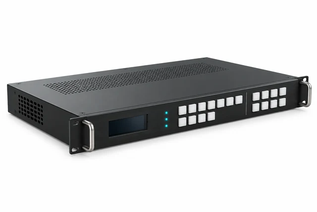
Both captured sources together; four unique output quadrants; saved-layout recall; seam-safe text; panel matching and single-panel replacement. Structure and electrical sign-off by the responsible trades; thermal operation at agreed conditions; restart and settings restoration.

Record supplied: Output/capture schedule, driver and licence record, layout backup, colour checks and service demonstration. Approved drawings, sign-offs, test report and open-item register.

These are planned project checks. The reference configuration has not passed physical system acceptance.

12Inputs and FAQ

Before we begin.

What to send us, and practical answers before the project starts.

Should we choose LED or LCD?

We compare content, viewing positions, ambient light, available dimensions and maintenance needs. LED forms a continuous pixel surface from cabinets. LCD uses a fixed panel grid with visible seams. The processing and control workflow is selected separately for either technology.

Is the larger LED example a 4K wall?

VW-02 has a native raster of 2752 × 1548. It can be fed through an agreed 4K HDMI timing, but accepting that signal does not turn the physical surface into a 3840 × 2160 display.

How do you choose pixel pitch?

We review the nearest viewer, the farthest viewer and the actual content together. Pixel pitch helps determine visible pixel structure, while text size and layout determine whether information is readable. A sample viewed at the intended distance is more useful than a universal distance-to-pitch promise.

Can the wall show several sources at once?

VW-03 is designed for two captured sources in approved layouts. VW-01 uses one full-surface source; VW-02 selects between two. Additional simultaneous windows require a defined compositor or a verified processing mode with sufficient input and layer capacity.

How much power and support does it need?

The answer follows the selected cabinet or panel specification, total quantity, operating mode and support design. The two LED examples have calculated cabinet counts and masses, but their cabinet power data still needs supplier confirmation. The estimate identifies that gap instead of substituting a guessed wattage.

Will it look right on camera?

That requires a test with the intended cameras, shutters, frame rates, working light and content. An LED refresh-rate specification alone cannot establish freedom from bands or moiré. Camera-critical use is a studio or live-production design task.

What happens if a part fails?

The effect depends on the failed part and the specified signal and power paths. The base examples have single controllers and no automatic backup route. A project can add defined resilience and compatible spares, with tests for each agreed failure case.

What should we send to start?

Send the wall dimensions, viewing positions, example content and source list, together with photographs or drawings showing the structure and service space. Tell us the operating hours and whether source windows, filming or automatic recovery matter to the project.

13Reference complexes

Related complexes.

Documented project experience, separate from the reference designs above. Each project sheet records its own scope and outcome.

All complexes
14Talk to us

Share your video wall brief.

Send wall dimensions, viewing positions, example content and your source list.