Share sources across your site with routes that operators can select and a network your IT team can support. Start with the source list, the display list and what must run at the same time.
AV over IP connects source encoders and display decoders through managed Ethernet switches. A source can serve several displays, while each display selects its own permitted route. We coordinate the source formats, endpoints, network, controls and operating responsibilities as one design.
The three reference configurations below distribute HDMI video with its accompanying audio. They use one compatible endpoint platform and one AV network segment. USB control of remote computers, independent networked audio, recording and browser streaming need their own agreed interfaces and capacity checks.
Reference designs · example quantities · project selection and system tests required. These are starting points for a project, not completed installations or fixed procurement packages.
Restore the affected building or core; optional spare fibre paths
Delivery status
Reference design; tests required
Reference configurations. Example quantities require project selection, compatibility checks and system acceptance tests. The 10 Gb/s links are calculated choices for these route matrices. They do not guarantee capacity for additional streams, USB, multiple windows or future endpoints. All three configurations use L2 media distribution; routing media between IP subnets is a separate design.
Follow the signal path for your configuration.
IP-01
Local source sharing
Reference design; tests required
Staff select either of two HDMI sources on each of four displays. One source may be shown on all four displays at once.
Typical local distribution: two source encoders and four display decoders on one managed switch.
Two HDMI sources feed two encoders, one switch and four decoders connected to four displays; the operator client and controller exchange commands and status.
SA
2 HDMI sources
EA
2 encoders - fixed TX
WA
1 access switch A
6 endpoint ports
PSE at least 225 W
DA
4 decoders - fixed RX
VA
4 displays
SA → EA2 HDMI with audio
EA → WA2 x 1G + PoE+
WA → DA4 x 1G + PoE+
DA → VA4 HDMI with audio
BASE: one L2 AV VLAN; management VLAN separate
Dashed control shares the physical Ethernet links
One selected primary video feed per decoder
USB, multiview, independent AoIP and streaming excluded
Control & status
Signal flow. Devices, connections and conditions follow the drawing.Open SVG ↗
All 8 connections · 7 devices and services
Choose a connection to read its endpoints, direction and interface. Repeated device IDs refer to the same equipment across views.
From · DA4 decoders - fixed RX
→
To · WA1 access switch A
6 endpoint ports
PSE at least 225 W
Direction: source → destination · IGMP membership + status
From · UA1 wired operator client
Local power
→
To · WA1 access switch A
6 endpoint ports
PSE at least 225 W
Direction: source → destination · 1G wired access
From · CTRL1 route controller
Local power; programmed UI + drivers
→
To · WA1 access switch A
6 endpoint ports
PSE at least 225 W
Direction: source → destination · commands via switch
From · WA1 access switch A
6 endpoint ports
PSE at least 225 W
→
To · CTRL1 route controller
Local power; programmed UI + drivers
Direction: source → destination · endpoint status via switch
From · GW1 client IT gateway interface
AV + management VLAN trunk
→
To · WA1 access switch A
6 endpoint ports
PSE at least 225 W
Typical local distribution: two source encoders and four display decoders on one managed switch.
Two HDMI sources feed two encoders, one switch and four decoders connected to four displays; the operator client and controller exchange commands and status.
EA
2 encoders - fixed TX
WA
1 access switch A
6 endpoint ports
PSE at least 225 W
DA
4 decoders - fixed RX
UA
1 wired operator client
Local power
CTRL
1 route controller
Local power; programmed UI + drivers
GW
1 client IT gateway interface
AV + management VLAN trunk
IT
Client IT services and administration
No media routing to corporate network
DA → WAIGMP membership + status
UA → WA1G wired access
CTRL → WAcommands via switch
WA → CTRLendpoint status via switch
GW → WAallowed unicast services
IT ↔ GWfirewall policy
WA → DAroute commands
EA → WAsource status
BASE: one L2 AV VLAN; management VLAN separate
Dashed control shares the physical Ethernet links
One selected primary video feed per decoder
USB, multiview, independent AoIP and streaming excluded
Typical architecture · not a project drawing
Workflow, boundaries and intended result
Composition
Two source encoders, four display decoders, one managed PoE+ access switch, one route controller and one wired operator client. The example includes six HDMI connections, endpoint network cabling and one local rack/power installation set. Two sources, four displays and the agreed IT service connection are client interfaces.
Boundaries
The six endpoints have fixed encoder or decoder roles. There is one selected video feed per display, with its source audio. The base has no inter-switch backbone or automatic network recovery. Remote keyboard/mouse control, multiview and recording are outside this scope.
Intended result
Operators can recall permitted routes and see endpoint status. Commissioning checks all eight source-to-display pairs and simultaneous viewing on all four displays.
Example equipment for IP-01
Example quantities for the selected configuration; final selection follows the approved design. A catalogue listing does not confirm stock, delivery time or complete-system compatibility.
Source encoders
2
One per simultaneous independent source; confirmed platform and input format
Display decoders
4
One per independent display; matched to encoder stream type
Managed PoE+ access switches
1
Port, multicast and total power budget checked for every location
Shared controller / operator clients
1 / 1
Supported endpoint control, licensed client access and status feedback
Local installation sets
1
Rack, mounting, cabling, power distribution, cooling and agreed UPS
IP-02
Two-floor distribution
Reference design; tests required
Each floor has three sources and four displays. Operators can select local or other-floor sources without moving patch cables.
Typical two-floor distribution with one calculated 10 Gb/s optical link.
Each floor has three encoders and four decoders, joined by access switches and a fibre link; two clients use one controller.
SA
3 HDMI sources
EA
3 encoders - fixed TX
WA
1 access switch A
7 endpoint ports
PSE at least 263 W
DA
4 decoders - fixed RX
VA
4 displays
SB
3 HDMI sources
EB
3 encoders - fixed TX
WB
1 access switch B
7 endpoint ports
PSE at least 263 W
DB
4 decoders - fixed RX
VB
4 displays
SA → EA3 HDMI with audio
EA → WA3 x 1G + PoE+
WA → DA4 x 1G + PoE+
DA → VA4 HDMI with audio
SB → EB3 HDMI with audio
EB → WB3 x 1G + PoE+
WB → DB4 x 1G + PoE+
DB → VB4 HDMI with audio
WA ↔ WB1 duplex fibre / 2 SFP+
10G each direction; budget 3.75G each
BASE: one L2 AV VLAN; management VLAN separate
Dashed control shares the physical Ethernet links
One selected primary video feed per decoder
USB, multiview, independent AoIP and streaming excluded
Control & status
Signal flow. Devices, connections and conditions follow the drawing.Open SVG ↗
All 12 connections · 11 devices and services
Choose a connection to read its endpoints, direction and interface. Repeated device IDs refer to the same equipment across views.
From · DA4 decoders - fixed RX
→
To · WA1 access switch A
7 endpoint ports
PSE at least 263 W
Direction: source → destination · IGMP membership + status
From · UA1 wired operator client
Local power
→
To · WA1 access switch A
7 endpoint ports
PSE at least 263 W
Direction: source → destination · 1G wired access
From · DB4 decoders - fixed RX
→
To · WB1 access switch B
7 endpoint ports
PSE at least 263 W
Direction: source → destination · IGMP membership + status
From · UB1 wired operator client
Local power
→
To · WB1 access switch B
7 endpoint ports
PSE at least 263 W
Direction: source → destination · 1G wired access
From · CTRL1 route controller
Local power; programmed UI + drivers
→
To · WA1 access switch A
7 endpoint ports
PSE at least 263 W
Direction: source → destination · commands via switch
From · WA1 access switch A
7 endpoint ports
PSE at least 263 W
→
To · CTRL1 route controller
Local power; programmed UI + drivers
Direction: source → destination · endpoint status via switch
From · GW1 client IT gateway interface
AV + management VLAN trunk
→
To · WA1 access switch A
7 endpoint ports
PSE at least 263 W
Typical two-floor distribution with one calculated 10 Gb/s optical link.
Each floor has three encoders and four decoders, joined by access switches and a fibre link; two clients use one controller.
EA
3 encoders - fixed TX
WA
1 access switch A
7 endpoint ports
PSE at least 263 W
DA
4 decoders - fixed RX
UA
1 wired operator client
Local power
EB
3 encoders - fixed TX
WB
1 access switch B
7 endpoint ports
PSE at least 263 W
DB
4 decoders - fixed RX
UB
1 wired operator client
Local power
CTRL
1 route controller
Local power; programmed UI + drivers
GW
1 client IT gateway interface
AV + management VLAN trunk
IT
Client IT services and administration
No media routing to corporate network
DA → WAIGMP membership + status
UA → WA1G wired access
DB → WBIGMP membership + status
UB → WB1G wired access
CTRL → WAcommands via switch
WA → CTRLendpoint status via switch
GW → WAallowed unicast services
IT ↔ GWfirewall policy
WA → DAroute commands
EA → WAsource status
WB → DBroute commands
EB → WBsource status
BASE: one L2 AV VLAN; management VLAN separate
Dashed control shares the physical Ethernet links
One selected primary video feed per decoder
USB, multiview, independent AoIP and streaming excluded
Typical architecture · not a project drawing
Workflow, boundaries and intended result
Composition
Six encoders, eight decoders, two managed PoE+ access switches, one duplex optical link with two 10 Gb/s transceivers, one shared controller and two wired operator clients. Fourteen HDMI connections and two local installation sets complete the example.
Boundaries
The calculation allows three different remote sources in each direction at once; displays may share a source. One AV VLAN extends between the switches. The base optical link is single, so its loss removes inter-floor distribution. Local operation during a controller or uplink failure is tested and documented rather than assumed.
Intended result
Eight displays can use an agreed mix of local and remote sources, supported by a tested route matrix and a measured inter-floor load. All 48 source-to-display pairs enter the acceptance schedule.
Example equipment for IP-02
Example quantities for the selected configuration; final selection follows the approved design. A catalogue listing does not confirm stock, delivery time or complete-system compatibility.
Source encoders
6
One per simultaneous independent source; confirmed platform and input format
Display decoders
8
One per independent display; matched to encoder stream type
Managed PoE+ access switches
2
Port, multicast and total power budget checked for every location
Duplex optical links / transceivers
1 / 2
Matched optical pair, distance and measured loss
Shared controller / operator clients
1 / 2
Supported endpoint control, licensed client access and status feedback
Local installation sets
2
Rack, mounting, cabling, power distribution, cooling and agreed UPS
IP-03
Three-building distribution
Reference design; tests required
Buildings A, B and C each contain four sources and six displays. A shared operator system controls routes across the site.
Typical three-building distribution; R01 spare links are a separate option.
Three groups of four encoders and six decoders connect through access switches to one core, with a central controller and one client per building.
SA
4 HDMI sources
EA
4 encoders - fixed TX
WA
1 access switch A
10 endpoint ports
PSE at least 375 W
DA
6 decoders - fixed RX
VA
6 displays
SB
4 HDMI sources
EB
4 encoders - fixed TX
WB
1 access switch B
10 endpoint ports
PSE at least 375 W
DB
6 decoders - fixed RX
VB
6 displays
SC
4 HDMI sources
EC
4 encoders - fixed TX
WC
1 access switch C
10 endpoint ports
PSE at least 375 W
DC
6 decoders - fixed RX
VC
6 displays
CORE
1 shared core
3 base fibre links / 6 SFP+
Single core; no core HA
SA → EA4 HDMI with audio
EA → WA4 x 1G + PoE+
WA → DA6 x 1G + PoE+
DA → VA6 HDMI with audio
SB → EB4 HDMI with audio
EB → WB4 x 1G + PoE+
WB → DB6 x 1G + PoE+
DB → VB6 HDMI with audio
SC → EC4 HDMI with audio
EC → WC4 x 1G + PoE+
WC → DC6 x 1G + PoE+
DC → VC6 HDMI with audio
WA ↔ CORE10G fibre
TX budget 5G / RX 7.5G
WB ↔ CORE10G fibre
TX budget 5G / RX 7.5G
WC ↔ CORE10G fibre
TX budget 5G / RX 7.5G
BASE: one L2 AV VLAN; management VLAN separate
Dashed control shares the physical Ethernet links
One selected primary video feed per decoder
USB, multiview, independent AoIP and streaming excluded
Control & status
Signal flow. Devices, connections and conditions follow the drawing.Open SVG ↗
All 17 connections · 17 devices and services
Choose a connection to read its endpoints, direction and interface. Repeated device IDs refer to the same equipment across views.
From · DA6 decoders - fixed RX
→
To · WA1 access switch A
10 endpoint ports
PSE at least 375 W
Direction: source → destination · IGMP membership + status
From · UA1 wired operator client
Local power
→
To · WA1 access switch A
10 endpoint ports
PSE at least 375 W
Direction: source → destination · 1G wired access
From · DB6 decoders - fixed RX
→
To · WB1 access switch B
10 endpoint ports
PSE at least 375 W
Direction: source → destination · IGMP membership + status
From · UB1 wired operator client
Local power
→
To · WB1 access switch B
10 endpoint ports
PSE at least 375 W
Direction: source → destination · 1G wired access
From · DC6 decoders - fixed RX
→
To · WC1 access switch C
10 endpoint ports
PSE at least 375 W
Direction: source → destination · IGMP membership + status
From · UC1 wired operator client
Local power
→
To · WC1 access switch C
10 endpoint ports
PSE at least 375 W
Direction: source → destination · 1G wired access
From · OPTOPTION R01 ONLY
+3 separate fibre paths / +6 SFP+
Second path per access to SAME core
RSTP: one path blocked; no 20G claim
→
To · CORE1 shared core
3 base fibre links / 6 SFP+
Single core; no core HA
Direction: source → destination · uses second uplink on A, B and C
From · CTRL1 route controller
Local power; programmed UI + drivers
→
To · CORE1 shared core
3 base fibre links / 6 SFP+
Single core; no core HA
Direction: source → destination · commands via switch
From · CORE1 shared core
3 base fibre links / 6 SFP+
Single core; no core HA
→
To · CTRL1 route controller
Local power; programmed UI + drivers
Direction: source → destination · endpoint status via switch
From · GW1 client IT gateway interface
AV + management VLAN trunk
→
To · CORE1 shared core
3 base fibre links / 6 SFP+
Single core; no core HA
Typical three-building distribution; R01 spare links are a separate option.
Three groups of four encoders and six decoders connect through access switches to one core, with a central controller and one client per building.
EA
4 encoders - fixed TX
WA
1 access switch A
10 endpoint ports
PSE at least 375 W
DA
6 decoders - fixed RX
UA
1 wired operator client
Local power
EB
4 encoders - fixed TX
WB
1 access switch B
10 endpoint ports
PSE at least 375 W
DB
6 decoders - fixed RX
UB
1 wired operator client
Local power
EC
4 encoders - fixed TX
WC
1 access switch C
10 endpoint ports
PSE at least 375 W
DC
6 decoders - fixed RX
UC
1 wired operator client
Local power
CORE
1 shared core
3 base fibre links / 6 SFP+
Single core; no core HA
OPT
OPTION R01 ONLY
+3 separate fibre paths / +6 SFP+
Second path per access to SAME core
RSTP: one path blocked; no 20G claim
CTRL
1 route controller
Local power; programmed UI + drivers
GW
1 client IT gateway interface
AV + management VLAN trunk
IT
Client IT services and administration
No media routing to corporate network
DA → WAIGMP membership + status
UA → WA1G wired access
DB → WBIGMP membership + status
UB → WB1G wired access
DC → WCIGMP membership + status
UC → WC1G wired access
OPT → COREuses second uplink on A, B and C
CTRL → COREcommands via switch
CORE → CTRLendpoint status via switch
GW → COREallowed unicast services
IT ↔ GWfirewall policy
WA → DAroute commands
EA → WAsource status
WB → DBroute commands
EB → WBsource status
WC → DCroute commands
EC → WCsource status
BASE: one L2 AV VLAN; management VLAN separate
Dashed control shares the physical Ethernet links
One selected primary video feed per decoder
USB, multiview, independent AoIP and streaming excluded
Typical architecture · not a project drawing
Workflow, boundaries and intended result
Composition
Twelve encoders, eighteen decoders, three managed PoE+ access switches, one shared core, three duplex fibre links with six 10 Gb/s transceivers, one shared controller and three wired operator clients. There are thirty HDMI connections, three access installation sets and one core installation set.
Boundaries
Each display receives one selected primary feed. The example permits up to six distinct incoming remote feeds and four outgoing local feeds per building. The core, controller and each endpoint are single devices. The separately selected R01 option adds a second fibre path to the same core for each building, with controlled link failover; it does not protect against a core or access-switch failure. Core redundancy or routed inter-building media requires a revised design.
Intended result
The site has an explicit routing and ownership plan for all eighteen displays. Acceptance covers all 216 source-to-display pairs, concurrent building traffic and the selected recovery scope.
Example equipment for IP-03
Example quantities for the selected configuration; final selection follows the approved design. A catalogue listing does not confirm stock, delivery time or complete-system compatibility.
Source encoders
12
One per simultaneous independent source; confirmed platform and input format
Display decoders
18
One per independent display; matched to encoder stream type
Managed PoE+ access switches
3
Port, multicast and total power budget checked for every location
Shared core switch
1
Optical port count and simultaneous multicast replication capacity
Duplex optical links / transceivers
3 / 6
Matched optical pair, distance and measured loss
Shared controller / operator clients
1 / 3
Supported endpoint control, licensed client access and status feedback
Local installation sets
4
Rack, mounting, cabling, power distribution, cooling and agreed UPS
05Reference architectureInteractive
How a typical system fits together.
Four layers, from the sources to the people operating the system. Select a layer to see its components and the interfaces between them.
Typical architecture · AV over IPSelect a layer to inspect it
HDMIEthernetHDMIIP
L2 · Selected layerProcessing & transport
How signals are routed and processed in a typical system of this kind.
06Design parametersTypical guidance · confirmed per project
What the design has to get right.
The engineering checks behind every drawing. Rules of thumb are starting points; the project values are confirmed with the people named.
Design parameters
No.
Parameter
Guidance
Rule of thumb
Confirmed with
D01
Independent feeds
Count sources and destinations separately
One encoder per source and one decoder per display; no simultaneous encoder/decoder double counting
AV designer
D02
Formats and protection
Record actual resolution, frame rate, colour format, audio and protected-content needs
Qualify every required end-to-end route; agree display EDID and content permissions
AV team and source owner
D03
Simultaneous routes
Specify which sources each display needs together
One primary feed per display in all three examples
Client and AV designer
D04
Backbone capacity
Budget unique subscribed streams per direction on every link
The example 10 Gb/s links apply only to the documented matrices
Network designer
D05
Switch ports and power
Count control and service links as well as AV endpoints
Reserve access ports and check total PSE budget with the installed power supplies
Network and electrical teams
D06
Multicast and VLANs
Agree membership, querier and forwarding behaviour
One L2 AV segment in the base; separate switch management and controlled IT access
IT team
D07
Delay and switching
Measure with the real source and display chain
Numerical acceptance limits are agreed before procurement
Client and commissioning engineer
D08
Resilience
List exactly which failures must be survived
Single core/controller in the base; R01 protects selected fibre-link failures only
Client and IT team
D09
Distance and optical loss
Survey the actual route and terminations
Match transceivers and fibre; verify the optical budget
Cabling contractor
D10
Expansion
Recalculate after adding endpoints or services
Spare ports alone do not establish spare media or power capacity
AV and IT teams
Common mistakes
And how the design process prevents them.
M01
Mistake: Counting one transceiver as an encoder and decoder at the same time
Prevention: Assign one operating role to every endpoint
M02
Mistake: Assuming all Ethernet AV devices interoperate
Prevention: Qualify the exact platform, stream type and firmware combination
M03
Mistake: Selecting the backbone from the display count alone
Prevention: Calculate distinct subscribed streams in both directions
M04
Mistake: Using per-port PoE capability as the switch's total power budget
Prevention: Check the installed PSE supply and all allocated loads
M05
Mistake: Connecting a spare fibre without a loop-control plan
Prevention: Configure and test the selected redundant topology
M06
Mistake: Treating a routed management interface as routed media support
Prevention: Document AV VLAN boundaries and design multicast routing separately
07Design referencesEditions checked per project
The references we design to.
Equipment documentation, industry guides and project requirements inform the design. Confirm applicable editions and acceptance criteria for the site.
Equipment documentation and industry guides04
IEEE 802.1Q — Bridges and Bridged NetworksProject design referenceVLAN boundaries and bridge topologyCheck current edition
IEEE 802.3 — EthernetProject design referenceCopper, optical and PoE interfaces; the selected endpoint requires Type 2 PoE+ powerCheck current edition
RFC 4541 — IGMP/MLD snooping considerationsProject design referenceInformational guidance for multicast forwarding; switch implementation still requires qualificationCheck current edition
RFC 9776 — Internet Group Management Protocol, Version 3Project design referenceIGMP reference; choose the version supported by the actual endpoint and switch configurationCheck current edition
Local and project requirements01
Client IT and ICT policiesProject design referenceAddressing, approved switches, cabling, access, software changes and support ownershipCheck current edition
08Integrations08 interfaces
Connected to the building and its IT.
The systems this solution usually exchanges signals or data with, and why. Each interface is agreed with the system owner.
I01
Existing room AV
HDMI from an agreed local output
Share the selected room programme; it is one encoded source, not all matrix inputs
I02
Corporate IT services
Allowed unicast services through a gateway/firewall
Addressing, time, name resolution and administration; no automatic media transit to corporate networks
I03
Operator control
Supported IP control interface
Select permitted routes and show endpoint feedback; client licences and programming included in final scope
I04
Signage players
HDMI from the player to an encoder
Distribute the player's selected content; playlist management stays with its CMS
I05
Recording or web streaming
Dedicated, compatible output and capture/streaming interface
Separate option; a platform's native multicast stream is not automatically browser or recorder compatible
I06
Remote computer operation
Qualified USB/KVM extension and host/device assignment
Separate option with its own peripherals, permissions and bandwidth budget
I07
Audio systems
HDMI audio, or a separately qualified audio interface
The base follows video audio; independent audio routing and clocking require separate design
I08
Facilities monitoring
Supported switch/controller alarms
Agreed power, temperature and link alarms; no assumed building-management protocol
09Delivery
From the brief to an accepted system.
The six stages follow the selected configuration. Platform development or unconfirmed software functions require their own agreed scope and validation milestones.
The test plan is agreed before procurement. Every result records equipment and firmware, source/display formats, the route set and pass limits. The example designs have not yet undergone these tests. - IP-01: all 8 source-to-display pairs, both sources active, and one source on all four displays. - IP-02: all 48 pairs, all eight displays active, and three distinct remote feeds in each direction at the same time. - IP-03: all 216 pairs, all eighteen displays active, and the designed worst-case incoming and outgoing building traffic. - Every configuration: picture and accompanying audio, source switching, EDID/HDCP where required, delay, PoE startup, multicast containment, status feedback and access permissions. - Recovery: agreed device restarts and backup restoration; for selected R01, fibre loss and restoration with measured interruption and no network loop. Single-device failures remain inside the stated recovery boundary.
Record supplied: Agreed criteria, equipment and version schedule, measured test results and recovery procedure.
These are planned project checks. The reference configuration has not passed physical system acceptance.
The test plan is agreed before procurement. Every result records equipment and firmware, source/display formats, the route set and pass limits. The example designs have not yet undergone these tests. - IP-01: all 8 source-to-display pairs, both sources active, and one source on all four displays. - IP-02: all 48 pairs, all eight displays active, and three distinct remote feeds in each direction at the same time. - IP-03: all 216 pairs, all eighteen displays active, and the designed worst-case incoming and outgoing building traffic. - Every configuration: picture and accompanying audio, source switching, EDID/HDCP where required, delay, PoE startup, multicast containment, status feedback and access permissions. - Recovery: agreed device restarts and backup restoration; for selected R01, fibre loss and restoration with measured interruption and no network loop. Single-device failures remain inside the stated recovery boundary.
Record supplied: Agreed criteria, equipment and version schedule, measured test results and recovery procedure.
These are planned project checks. The reference configuration has not passed physical system acceptance.
The test plan is agreed before procurement. Every result records equipment and firmware, source/display formats, the route set and pass limits. The example designs have not yet undergone these tests. - IP-01: all 8 source-to-display pairs, both sources active, and one source on all four displays. - IP-02: all 48 pairs, all eight displays active, and three distinct remote feeds in each direction at the same time. - IP-03: all 216 pairs, all eighteen displays active, and the designed worst-case incoming and outgoing building traffic. - Every configuration: picture and accompanying audio, source switching, EDID/HDCP where required, delay, PoE startup, multicast containment, status feedback and access permissions. - Recovery: agreed device restarts and backup restoration; for selected R01, fibre loss and restoration with measured interruption and no network loop. Single-device failures remain inside the stated recovery boundary.
Record supplied: Agreed criteria, equipment and version schedule, measured test results and recovery procedure.
These are planned project checks. The reference configuration has not passed physical system acceptance.
11Inputs and FAQ
Before we begin.
What to send us, and practical answers before the project starts.
Can we use our existing network?
Possibly. We review switch features, current loading, available ports, power, fibre and IT policies. A VLAN provides separation but does not create bandwidth or prove multicast compatibility.
Does a 10 Gb/s backbone cover every system?
No. In IP-02 and IP-03 it follows the stated source and display arrangement, with one primary feed per display. Extra streams, USB or new endpoints require a new calculation and load test.
Can encoders and decoders from different platforms work together?
Only when their exact media and control interfaces have been qualified together. Ethernet connectivity alone establishes no media compatibility, even when the connectors and advertised resolution match.
Can one endpoint send and receive two independent pictures?
The endpoints selected for these examples operate as an encoder or a decoder. A room that must send one source and receive another independently needs separate endpoints in this design.
Does this include USB, KVM or web streaming?
The base distributes video and accompanying audio to displays. Remote USB control and browser streaming are separate workflows that need qualified interfaces, permissions and additional capacity where applicable.
Can the system cross subnets or link buildings?
Fibre links connect the buildings in IP-03 while keeping media within one L2 AV segment. Routed L3 distribution is possible only after a separate multicast, discovery, control and security design for the selected platform.
What happens when a link or switch fails?
The base has single links and devices. The affected paths may be unavailable until restoration. IP-03's optional R01 spare fibre paths address link failures to the same core; they do not duplicate the core, access switches, endpoints or controller. Agreed interruption limits are tested.
Who runs the system after handover?
A written support boundary assigns switch, endpoint, control, account and firmware duties. Operators receive a route guide; administrators receive configurations, test records and a recovery procedure.
12From our team’s projectsRC-08 · working drawing, anonymised
The working drawing, as we issue it.
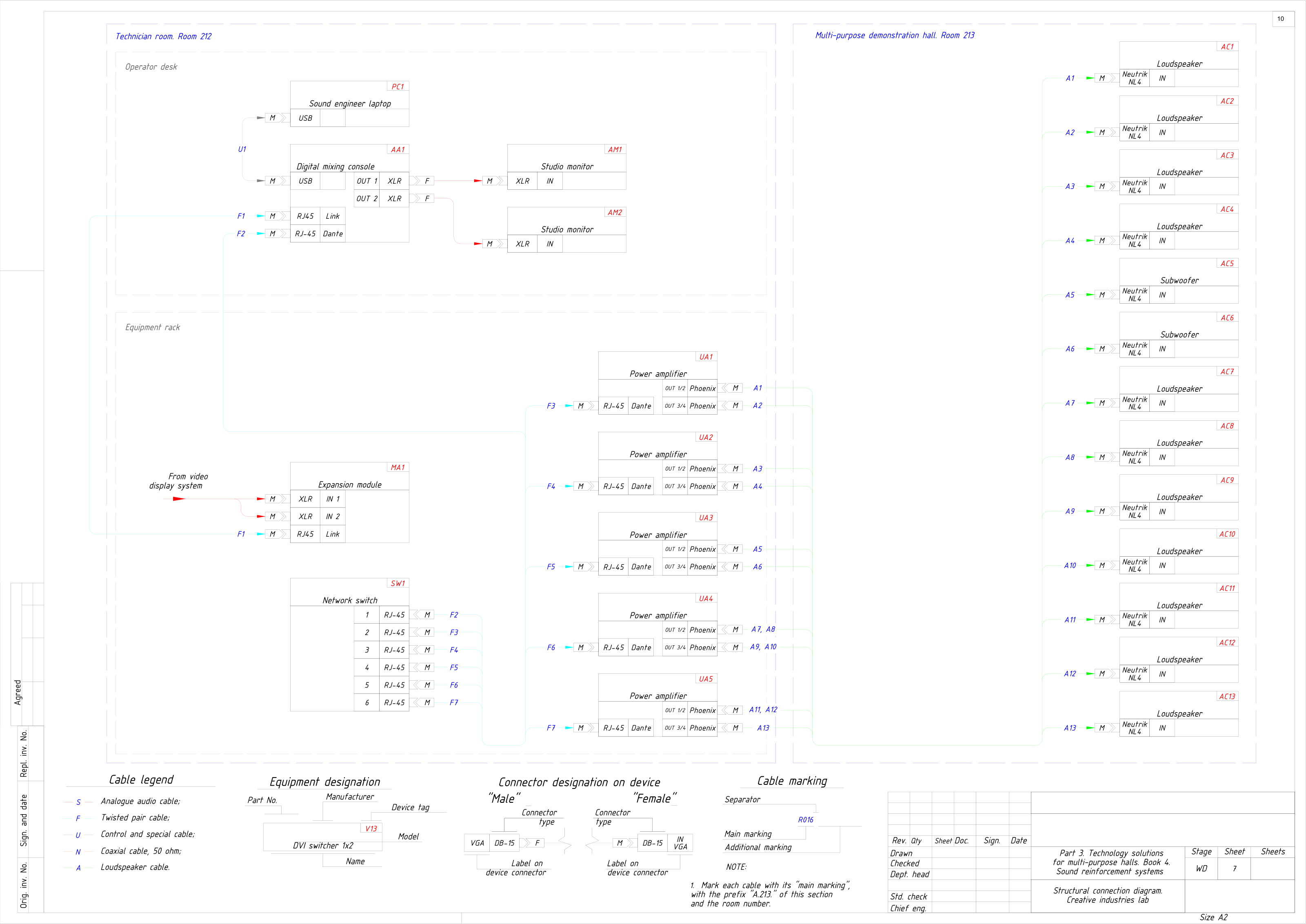
A demonstration hall of RC‑08 run over Dante: the console, an expansion module and five network amplifiers on one switch, feeding eleven loudspeakers and two subwoofers. Audio travels as network streams from the console to every amplifier.