Sheet 01 — Meeting & conference rooms
Solution 01 · Meeting & conference rooms

Bring everyone into the conversation.

Help people in the room and online see the material, hear each other and take part. Choose a laptop-led room, a dedicated room PC or a larger room with two selectable camera views and coordinated controls.

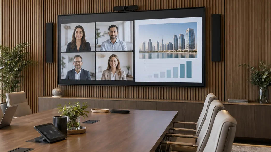
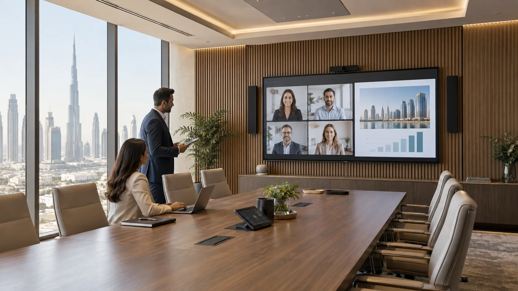
Concept visualisation of a Dubai executive boardroom with integrated hybrid meeting technology
Fig. 01.0 — Meeting & conference rooms
01Overview

Start with how the meeting runs.

A guest who brings a laptop, a team using a permanent room PC and a room running a managed conferencing platform need different connections and support arrangements. We define who starts the meeting, how content is shared and how users select the camera, microphone and sound.

Displays follow the seating and the smallest detail people need to read. Microphones and loudspeakers follow the room acoustics and positions of the participants. Controls should make the agreed workflow easy to repeat, with a clear indication of what is muted and which camera is in use.

Reference designs · project selection and system tests required. The three configurations below describe intended functions and example quantities. They are starting points for design, not fixed product bundles or evidence of completed installations. Room dimensions and seat counts are planning assumptions, not guaranteed equipment coverage.

Training, public events and divisible halls need their own operating brief. Learning & presentation spaces covers teaching workflows. Multi-purpose halls covers event changeovers and stage operation.

Three ways to host a meeting

Choose the hosting workflow before selecting the room equipment.

Three ways to host a meeting
Operating modeWhere the call runsWhat must be agreed
BYODThe user's laptopSupported laptops, USB camera/audio, display connection and user access; MR-01 baseline
Dedicated room PCA permanent PC running the selected conferencing applicationRoom account, permitted shared-device use, licences, updates and user operation; MR-02/03 baseline
Managed room platformA purpose-selected room system and consoleCertified system/peripheral combination where required, room licences, calendar and management; separately selected alternative

A permanent PC does not become a certified Microsoft Teams Rooms or Zoom Rooms system simply by connecting room peripherals. If a managed room platform is required, we select and verify that complete configuration. Scheduled join, booking panels and platform-specific multi-camera features are not included by default.

02Where it is used06 environments

Real environments, real priorities.

Who works in each kind of space, what they work with and what matters most to them.

Application register
No.EnvironmentWho uses itWork and contentWhat matters mostTypical systems
A01Small team roomColleagues and remote guestsShort calls and document reviewStraightforward laptop connectionMR-01: one display and a USB video bar
A02Guest meeting roomVisiting presenters and local staffCalls hosted from a visitor's laptopTested connectors and clear instructionsMR-01 with an agreed laptop adapter set
A03Project meeting roomA regular team and remote colleaguesRecurring hybrid meetingsPermanent PC and consistent sound routingMR-02: ceiling microphone, camera and room sound
A04Interview roomInterviewers and remote candidatesConversation and screen sharingCamera framing, privacy and mute indicationMR-02 with agreed viewing and microphone zones
A05BoardroomParticipants around a longer tableDiscussion and document reviewTwo selectable views and readable displaysMR-03: two cameras, two microphone arrays and controls
A06Client briefing roomPresenters, stakeholders and remote teamsDemonstrations and detailed materialDisplay layout and controlled camera presetsMR-03 with content and sightlines checked
03Typical configurations

Three starting points, compared.

Choose the workflow closest to your brief. Compare its scope, interfaces and operating limits before selecting equipment.

Compare all 3 configurations
Configuration

Laptop-led meeting

MR-01

Connect a laptop to one display and a USB video bar. Reference design; laptop and room tests required.

Explore MR-01

Dedicated room PC

MR-02

Run recurring calls with a ceiling microphone and a separate camera. Reference design; platform and room tests required.

Explore MR-02

Conference room with two camera views

MR-03

Select the useful camera view and operate sound and display presets. Reference design; camera selection, controls and room tests required.

Explore MR-03
Primary task

Start the call from a guest laptop

Run recurring calls from a permanent PC

Run a larger meeting with selectable views and coordinated controls

Example room

About 4 × 4 m; 4–6 seats assumed

About 6 × 4 m; 8–12 seats assumed

About 8 × 5 m; 16–20 seats assumed

Call host

User's laptop

One dedicated room PC

One dedicated room PC

Displays

One; 65-inch candidate

One; 75-inch candidate

Two; 86-inch candidates

Camera path

One integrated USB video bar

One SDI camera through one USB capture device

Two SDI cameras through two USB capture devices

Speech and sound

Microphones, speakers and processing in the bar

One ceiling array, one USB audio processor and two powered network speakers

Two ceiling arrays, one USB audio/control processor and four powered network speakers

Echo cancellation

In the video bar

In the ceiling array; playback returned as its reference

In both ceiling arrays; playback returned to both as reference

Operation

Laptop application and local device controls

PC application; camera presets through an approved control utility

Camera selection in the call application; room panel for presets, sound and displays

Guest device takeover

Included through the agreed USB and HDMI connections

Additional interface and switching scope

Additional interface and switching scope

Managed room platform

Separate alternative

Separate alternative

Separate alternative

Delivery status

Reference design; laptop and room tests required

Reference design; platform and room tests required

Reference design; camera selection, controls and room tests required
Laptop-led meeting

MR-01

Connect a laptop to one display and a USB video bar. Reference design; laptop and room tests required.

Explore MR-01
Primary task
Start the call from a guest laptop
Example room
About 4 × 4 m; 4–6 seats assumed
Call host
User's laptop
Displays
One; 65-inch candidate
Camera path
One integrated USB video bar
Speech and sound
Microphones, speakers and processing in the bar
Echo cancellation
In the video bar
Operation
Laptop application and local device controls
Guest device takeover
Included through the agreed USB and HDMI connections
Managed room platform
Separate alternative
Delivery status
Reference design; laptop and room tests required

Dedicated room PC

MR-02

Run recurring calls with a ceiling microphone and a separate camera. Reference design; platform and room tests required.

Explore MR-02
Primary task
Run recurring calls from a permanent PC
Example room
About 6 × 4 m; 8–12 seats assumed
Call host
One dedicated room PC
Displays
One; 75-inch candidate
Camera path
One SDI camera through one USB capture device
Speech and sound
One ceiling array, one USB audio processor and two powered network speakers
Echo cancellation
In the ceiling array; playback returned as its reference
Operation
PC application; camera presets through an approved control utility
Guest device takeover
Additional interface and switching scope
Managed room platform
Separate alternative
Delivery status
Reference design; platform and room tests required

Conference room with two camera views

MR-03

Select the useful camera view and operate sound and display presets. Reference design; camera selection, controls and room tests required.

Explore MR-03
Primary task
Run a larger meeting with selectable views and coordinated controls
Example room
About 8 × 5 m; 16–20 seats assumed
Call host
One dedicated room PC
Displays
Two; 86-inch candidates
Camera path
Two SDI cameras through two USB capture devices
Speech and sound
Two ceiling arrays, one USB audio/control processor and four powered network speakers
Echo cancellation
In both ceiling arrays; playback returned to both as reference
Operation
Camera selection in the call application; room panel for presets, sound and displays
Guest device takeover
Additional interface and switching scope
Managed room platform
Separate alternative
Delivery status
Reference design; camera selection, controls and room tests required
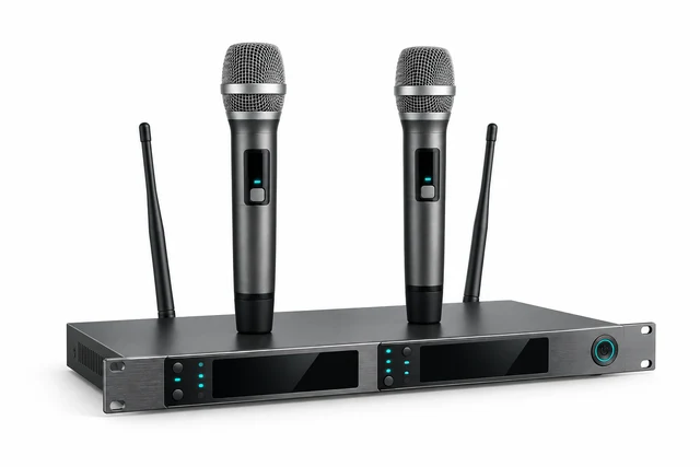
Reference configurations. Example quantities require project selection, compatibility checks and system acceptance tests. The display diagonals are candidates for sightline and content checks. Two displays do not guarantee separate people/content views in every application. Two cameras provide a choice of views; automatic speaker tracking and simultaneous multi-camera transmission are additional design requirements.

Follow the signal path for your configuration.

MR-01

Laptop-led meeting

Reference design; laptop and room tests required

A guest or employee uses their laptop to start a call and share material in a small room.

MR-01 · Laptop-led meeting

The laptop sends HDMI to the display and exchanges camera, microphone and playback audio with a USB video bar.

Signal flow

Signal flow. Devices, connections and conditions follow the drawing.Open SVG ↗
MR-01 · Signal flowLaptop HDMI directly to the display and USB camera, microphone and playback through one video bar. Local controls and separate power supplies. No room PC or managed platform in this baseline. HDMI and USB are separate; laptop charging is separate. Reference design: project selection and tests required. Repeated device identifiers refer to the same equipment across views. Equipment illustrations are schematic; labels define quantities.{"sourceHash":"b45d0c90a9790d1547dde74827566ab543849f32e98cf81845384945b54fd141","view":"signal","nodes":["PC","DIS","BAR","REM"],"edges":["L01","L02","L03","L04"]}PIXEL COMMAND SOLUTIONS / MR-01 / SIGNAL FLOWSignal flowREFERENCE DESIGN · PROJECT VALIDATION REQUIREDPC → DIS: HDMI: selected materialHDMI: selected materialBAR → PC: USB camera + processed microphoneUSB camera + processedmicrophonePC → BAR: USB playback; internal AEC referenceUSB playbackPC ↔ REM: IP call via client networkIP call via clientnetwork1 user laptop Call application and screen sharingPC1 user laptop1 display 65-inch candidate; speakers offDIS1 display1 USB video bar Camera, microphones, AEC, speakersBAR1 USB video barRemote participants Client conferencing serviceREMRemote participantsVideo / LED dataUSB / KVMNetwork / data
Devices, connections & design conditions 4 connections
  • The laptop sends HDMI to the display and exchanges camera, microphone and playback audio with a USB video bar.
  • MR-01 reference diagram with separate HDMI and USB paths, local controls and the laptop's network call.
PC
1 user laptop Call application and screen sharing
DIS
1 display 65-inch candidate; speakers off
BAR
1 USB video bar Camera, microphones, AEC, speakers
REM
Remote participants Client conferencing service
  1. PC → DISHDMI: selected material
  2. BAR → PCUSB camera + processed microphone
  3. PC → BARUSB playback; internal AEC reference
  4. PC ↔ REMIP call via client network

No room PC or managed platform in this baseline. HDMI and USB are separate; laptop charging is separate. Reference design: project selection and tests required.

Control & power

Signal flow. Devices, connections and conditions follow the drawing.Open SVG ↗
MR-01 · Control & powerLaptop HDMI directly to the display and USB camera, microphone and playback through one video bar. Local controls and separate power supplies. No room PC or managed platform in this baseline. HDMI and USB are separate; laptop charging is separate. Reference design: project selection and tests required. Repeated device identifiers refer to the same equipment across views. Equipment illustrations are schematic; labels define quantities.{"sourceHash":"b45d0c90a9790d1547dde74827566ab543849f32e98cf81845384945b54fd141","view":"control","nodes":["PC","DIS","BAR","OP","POWER"],"edges":["L05","L06","L07","L08","L09"]}PIXEL COMMAND SOLUTIONS / MR-01 / CONTROL & POWERControl & powerREFERENCE DESIGN · PROJECT VALIDATION REQUIREDOP → PC: Start, share, device selectionStart, share,device selectionOP → BAR: Local mute / level; verify stateLocal mute / levelOP → DIS: Power / inputPower / inputPOWER → BAR: Separate power suppliesSeparate powersuppliesPOWER → DIS: ACAC1 user laptop Call application and screen sharingPC1 user laptop1 display 65-inch candidate; speakers offDIS1 display1 USB video bar Camera, microphones, AEC, speakersBAR1 USB video barUser operation Laptop UI; local device controlsOPUser operationRoom power and installation Display and bar supplies; laptop chargerPOWERRoom power andinstallationControl / statusPower
Devices, connections & design conditions 5 connections
  • The laptop sends HDMI to the display and exchanges camera, microphone and playback audio with a USB video bar.
  • MR-01 reference diagram with separate HDMI and USB paths, local controls and the laptop's network call.
PC
1 user laptop Call application and screen sharing
DIS
1 display 65-inch candidate; speakers off
BAR
1 USB video bar Camera, microphones, AEC, speakers
OP
User operation Laptop UI; local device controls
POWER
Room power and installation Display and bar supplies; laptop charger
  1. OP → PCStart, share, device selection
  2. OP → BARLocal mute / level; verify state
  3. OP → DISPower / input
  4. POWER → BARSeparate power supplies
  5. POWER → DISAC

No room PC or managed platform in this baseline. HDMI and USB are separate; laptop charging is separate. Reference design: project selection and tests required.

Typical architecture · not a project drawing

Workflow, boundaries and intended result

Composition

One display, one USB video bar with camera, microphones, speakers and echo cancellation, and the user's laptop. Separate USB and HDMI paths connect the room devices. The installation includes mounting, power, labelled cables and agreed laptop adapters where required.

Boundaries

The laptop supplies the meeting application, account and network connection. Laptop charging is separate unless a compatible powered dock is selected. A permanent PC, ceiling microphones, network speakers, room console and booking service are outside the baseline. Supported laptop/OS combinations are agreed and tested.

Intended result

A user connects the laptop, selects the room video and audio devices, starts the meeting and shares material on the room display and through the application.

Example equipment for MR-01

Example quantities for the selected configuration; final selection follows the approved design. A catalogue listing does not confirm stock, delivery time or complete-system compatibility.

Display
1

Commercial display requirements confirmed per room

User laptop / dedicated room PC
1 user laptop

Selected with IT

Integrated USB video bar
1

Selected for the agreed laptop and room

Installation set
1

Cables, mounts, power and labels by surveyed routes

Software and entitlements
User application

Version and licence schedule

MR-02

Dedicated room PC

Reference design; platform and room tests required

A regular team starts recurring calls from a permanent PC, with a ceiling microphone and a separate camera positioned for the seating.

MR-02 · Dedicated room PC

An SDI camera reaches the PC through USB capture. The ceiling array sends processed speech; playback feeds two speakers and the array's echo reference.

Signal flow

Signal flow. Devices, connections and conditions follow the drawing.Open SVG ↗
MR-02 · Signal flowSDI to USB capture; processed ceiling microphone to USB send; playback to speakers and AEC reference through the room switch. Separate PC camera and display controls. USB playback is excluded from USB microphone send. No local voice lift, guest takeover or room panel in the baseline. Reference design: no system tests performed. Repeated device identifiers refer to the same equipment across views. Equipment illustrations are schematic; labels define quantities.{"sourceHash":"111805cc7cb2f7c1738efbf98b8c232f82bcacdd7c87f6d198ea1c3bbc8208ec","view":"signal","nodes":["CAM","CAP","PC","DIS","REM","MIC","DSP","SPK"],"edges":["L01","L02","L03","L04","L05","L06","L07","L08","L09"]}PIXEL COMMAND SOLUTIONS / MR-02 / SIGNAL FLOWSignal flowREFERENCE DESIGN · PROJECT VALIDATION REQUIREDCAM → CAP: 3G-SDI; BNC / capture adapter3G-SDICAP → PC: USB 3 video; 1080p30 targetUSB 3 videoPC → DIS: HDMIHDMIPC ↔ REM: IP call; content shared in applicationIP callMIC → DSP: Dante: 1 processed automixDante: 1 processedautomixDSP → SPK: Dante TX1: playbackDante TX1: playbackDSP → MIC: Dante TX2: playback to AEC referenceDante TX2: playback toAEC referenceDSP → PC: USB send: local speech onlyUSB send: local speechonlyPC → DSP: USB playback: far end + contentUSB playback: far end +content1 SDI PTZ camera Separate 12 V supplyCAM1 SDI PTZ camera1 SDI-to-USB capture Host powered; embedded audio offCAP1 SDI-to-USB capture1 dedicated room PC Call UI, sharing and PTZ utilityPC1 dedicated room PC1 display 75-inch candidate; speakers offDIS1 displayRemote participants / serviceREMRemote participants /service1 ceiling microphone array AEC ON; automatic coverage ONMIC1 ceiling microphonearray1 USB audio processor Input 9 to USB send; no second AECDSP1 USB audio processor2 powered network speakers Same mono playback busSPK2 powered networkspeakersVideo / LED dataUSB / KVMAudio
Devices, connections & design conditions 9 connections
  • An SDI camera reaches the PC through USB capture. The ceiling array sends processed speech; playback feeds two speakers and the array's echo reference.
  • MR-02 reference diagram showing SDI-to-USB capture, microphone AEC, USB audio, Dante routes, PoE and PC controls.
CAM
1 SDI PTZ camera Separate 12 V supply
CAP
1 SDI-to-USB capture Host powered; embedded audio off
PC
1 dedicated room PC Call UI, sharing and PTZ utility
DIS
1 display 75-inch candidate; speakers off
REM
Remote participants / service
MIC
1 ceiling microphone array AEC ON; automatic coverage ON
DSP
1 USB audio processor Input 9 to USB send; no second AEC
SPK
2 powered network speakers Same mono playback bus
  1. CAM → CAP3G-SDI; BNC / capture adapter
  2. CAP → PCUSB 3 video; 1080p30 target
  3. PC → DISHDMI
  4. PC ↔ REMIP call; content shared in application
  5. MIC → DSPDante: 1 processed automix
  6. DSP → SPKDante TX1: playback
  7. DSP → MICDante TX2: playback to AEC reference
  8. DSP → PCUSB send: local speech only
  9. PC → DSPUSB playback: far end + content

USB playback is excluded from USB microphone send. No local voice lift, guest takeover or room panel in the baseline. Reference design: no system tests performed.

Control & power

Signal flow. Devices, connections and conditions follow the drawing.Open SVG ↗
MR-02 · Control & powerSDI to USB capture; processed ceiling microphone to USB send; playback to speakers and AEC reference through the room switch. Separate PC camera and display controls. USB playback is excluded from USB microphone send. No local voice lift, guest takeover or room panel in the baseline. Reference design: no system tests performed. Repeated device identifiers refer to the same equipment across views. Equipment illustrations are schematic; labels define quantities.{"sourceHash":"111805cc7cb2f7c1738efbf98b8c232f82bcacdd7c87f6d198ea1c3bbc8208ec","view":"control","nodes":["CAM","PC","DIS","SW","NW"],"edges":["L10","L11","L12"]}PIXEL COMMAND SOLUTIONS / MR-02 / CONTROL & POWERControl & powerREFERENCE DESIGN · PROJECT VALIDATION REQUIREDPC → CAM: VISCA/IP presets; verified utilityVISCA/IP presetsPC → DIS: Agreed display IP control / statusAgreed display IPcontrol / statusSW → NW: Physical connections; see port schedulePhysical connections1 SDI PTZ camera Separate 12 V supplyCAM1 SDI PTZ camera1 dedicated room PC Call UI, sharing and PTZ utilityPC1 dedicated room PC1 display 75-inch candidate; speakers offDIS1 display1 managed room switch 8 copper links used; require at least 10 4 PoE devices; PSE at least 150 WSW1 managed room switchPhysical port schedule 1 array + 1 processor + 2 speakers: Ethernet and PoE PC + camera + display + uplink: Ethernet onlyNWPhysical port scheduleControl / statusPower
Devices, connections & design conditions 3 connections
  • An SDI camera reaches the PC through USB capture. The ceiling array sends processed speech; playback feeds two speakers and the array's echo reference.
  • MR-02 reference diagram showing SDI-to-USB capture, microphone AEC, USB audio, Dante routes, PoE and PC controls.
CAM
1 SDI PTZ camera Separate 12 V supply
PC
1 dedicated room PC Call UI, sharing and PTZ utility
DIS
1 display 75-inch candidate; speakers off
SW
1 managed room switch 8 copper links used; require at least 10 4 PoE devices; PSE at least 150 W
NW
Physical port schedule 1 array + 1 processor + 2 speakers: Ethernet and PoE PC + camera + display + uplink: Ethernet only
  1. PC → CAMVISCA/IP presets; verified utility
  2. PC → DISAgreed display IP control / status
  3. SW → NWPhysical connections; see port schedule

USB playback is excluded from USB microphone send. No local voice lift, guest takeover or room panel in the baseline. Reference design: no system tests performed.

Typical architecture · not a project drawing

Workflow, boundaries and intended result

Composition

One room PC, one display, one ceiling microphone array, one USB audio processor, two powered network loudspeakers, one SDI PTZ camera and one SDI-to-USB capture device. One managed PoE switch carries room audio and control. The PC includes keyboard/mouse operation using the main display; no additional operator monitor is assumed. Software, power supplies, mounting and installation connections are scheduled separately.

Boundaries

The microphone supplies the baseline echo cancellation; the processor routes its processed mix to the call and returns playback to the speakers and microphone reference input. Local speech reinforcement is outside this baseline. Users operate the call and camera presets from approved PC software. A touch controller is optional. Application mute and any separate room mute must be tested on the actual outgoing audio path; shared mute indication is not assumed. Guest USB takeover, automatic tracking, recording and managed-room enrolment are separate scope.

Intended result

Users can start the approved application, frame the agreed seating and conduct a call with tested speech pickup, playback and content sharing.

Example equipment for MR-02

Example quantities for the selected configuration; final selection follows the approved design. A catalogue listing does not confirm stock, delivery time or complete-system compatibility.

Display
1

Commercial display requirements confirmed per room

User laptop / dedicated room PC
1 room PC

Selected with IT

Ceiling microphone array
1

Microphones — interfaces and coverage by specification

USB audio processor
1

Audio processing

Powered network speaker
2

Network audio — compatible powered endpoints required

SDI PTZ camera / USB capture
1 / 1

Conference equipment; capture selected separately

Room panel
Optional

Selected with the control processor

Managed room PoE switch
1

Port and power schedule, agreed with IT

Installation set
1

Cables, mounts, power and labels by surveyed routes

Software and entitlements
Room application and camera control

Version and licence schedule

MR-03

Conference room with two camera views

Reference design; camera selection, controls and room tests required
A larger meeting uses two camera positions, two displays and a room panel for repeatable presets and sound controls.

MR-03 · Conference room with two camera views

Two captures feed the PC for manual camera selection. Two processed microphone mixes feed the call, while playback returns to four speakers and both echo references.

Signal flow

Signal flow. Devices, connections and conditions follow the drawing.Open SVG ↗
MR-03 · Signal flowTwo SDI to USB cameras, two displays, two processed microphone mixes, four speakers and an IP panel. Dante passes through one room switch. Camera selection remains in the PC application. Playback never enters the USB microphone send. No automatic tracking, local voice lift or certified room platform claimed. Panel presets and application camera selection are separate actions. Reference design: project selection and tests required. Repeated device identifiers refer to the same equipment across views. Equipment illustrations are schematic; labels define quantities.{"sourceHash":"e84a027f6be4fd6652651514ce8fe93e6a29fad3538afd6b54a371d9b6c3f4f9","view":"signal","nodes":["CAM","CAP","PC","DIS","REM","MIC","DSP","SPK"],"edges":["L01","L02","L03","L04","L05","L06","L07","L08","L09"]}PIXEL COMMAND SOLUTIONS / MR-03 / SIGNAL FLOWSignal flowREFERENCE DESIGN · PROJECT VALIDATION REQUIREDCAM → CAP: 2 separate 3G-SDI lines2 separate 3G-SDIlinesCAP → PC: 2 USB 3 video paths; test host topology2 USB 3 video pathsPC → DIS: 2 HDMI outputs; layout depends on app2 HDMI outputsPC ↔ REM: IP call and application content sharingIP call and applicationcontent sharingMIC → DSP: Dante: 2 processed automixes to RX1 / RX2Dante: 2 processedautomixes to RX1 / RX2DSP → SPK: TX1 multicast: 1 flow to 4 speakersTX1 multicast: 1 flowto 4 speakersDSP → MIC: TX2 multicast: 1 flow to both AEC referencesTX2 multicast: 1 flowto both AEC referencesDSP → PC: USB send: mixed local speech onlyUSB send: mixed localspeech onlyPC → DSP: USB playback: far end + contentUSB playback: far end +content2 SDI PTZ cameras Separate 12 V supply per cameraCAM2 SDI PTZ cameras2 SDI-to-USB captures One per camera; embedded audio offCAP2 SDI-to-USB captures1 dedicated room PC Manual camera selection in call appPC1 dedicated room PC2 displays 86-inch candidates; independent outputsDIS2 displaysRemote participants / service One selected camera in baselineREMRemote participants /service2 ceiling microphone arrays AEC and automatic coverage ON in eachMIC2 ceiling microphonearrays1 USB audio / control processor 2 active Dante RX + 2 TX; no second AECDSP1 USB audio / controlprocessor4 powered network speakers Same mono playback busSPK4 powered networkspeakersVideo / LED dataUSB / KVMAudio
Devices, connections & design conditions 9 connections
  • Two captures feed the PC for manual camera selection. Two processed microphone mixes feed the call, while playback returns to four speakers and both echo references.
  • MR-03 reference diagram showing two cameras and displays, two microphone arrays, audio return, room controls and the managed network.
CAM
2 SDI PTZ cameras Separate 12 V supply per camera
CAP
2 SDI-to-USB captures One per camera; embedded audio off
PC
1 dedicated room PC Manual camera selection in call app
DIS
2 displays 86-inch candidates; independent outputs
REM
Remote participants / service One selected camera in baseline
MIC
2 ceiling microphone arrays AEC and automatic coverage ON in each
DSP
1 USB audio / control processor 2 active Dante RX + 2 TX; no second AEC
SPK
4 powered network speakers Same mono playback bus
  1. CAM → CAP2 separate 3G-SDI lines
  2. CAP → PC2 USB 3 video paths; test host topology
  3. PC → DIS2 HDMI outputs; layout depends on app
  4. PC ↔ REMIP call and application content sharing
  5. MIC → DSPDante: 2 processed automixes to RX1 / RX2
  6. DSP → SPKTX1 multicast: 1 flow to 4 speakers
  7. DSP → MICTX2 multicast: 1 flow to both AEC references
  8. DSP → PCUSB send: mixed local speech only
  9. PC → DSPUSB playback: far end + content

Playback never enters the USB microphone send. No automatic tracking, local voice lift or certified room platform claimed. Panel presets and application camera selection are separate actions. Reference design: project selection and tests required.

Control & power

Signal flow. Devices, connections and conditions follow the drawing.Open SVG ↗
MR-03 · Control & powerTwo SDI to USB cameras, two displays, two processed microphone mixes, four speakers and an IP panel. Dante passes through one room switch. Camera selection remains in the PC application. Playback never enters the USB microphone send. No automatic tracking, local voice lift or certified room platform claimed. Panel presets and application camera selection are separate actions. Reference design: project selection and tests required. Repeated device identifiers refer to the same equipment across views. Equipment illustrations are schematic; labels define quantities.{"sourceHash":"e84a027f6be4fd6652651514ce8fe93e6a29fad3538afd6b54a371d9b6c3f4f9","view":"control","nodes":["CAM","DIS","DSP","PANEL","SW","NW"],"edges":["L10","L11","L12","L13","L14"]}PIXEL COMMAND SOLUTIONS / MR-03 / CONTROL & POWERControl & powerREFERENCE DESIGN · PROJECT VALIDATION REQUIREDPANEL → DSP: IP commandsIP commandsDSP → PANEL: Confirmed device status / faultConfirmed device status/ faultDSP → CAM: VISCA/IP presets; not app camera selectVISCA/IP presetsDSP → DIS: Agreed IP commands / statusAgreed IP commands /statusSW → NW: Physical connections; see port schedulePhysical connections2 SDI PTZ cameras Separate 12 V supply per cameraCAM2 SDI PTZ cameras2 displays 86-inch candidates; independent outputsDIS2 displays1 USB audio / control processor 2 active Dante RX + 2 TX; no second AECDSP1 USB audio / controlprocessor1 IP room panel Sound, PTZ presets, display controlsPANEL1 IP room panel1 managed room switch 14 copper links used; require at least 16 7 PoE devices; PSE at least 240 WSW1 managed room switchPhysical port schedule 2 arrays + 4 speakers + panel: Ethernet and PoE Processor + PC + 2 cameras + 2 displays + uplink: Ethernet only AV VLAN: configured multicast and querierNWPhysical port scheduleControl / statusPower
Devices, connections & design conditions 5 connections
  • Two captures feed the PC for manual camera selection. Two processed microphone mixes feed the call, while playback returns to four speakers and both echo references.
  • MR-03 reference diagram showing two cameras and displays, two microphone arrays, audio return, room controls and the managed network.
CAM
2 SDI PTZ cameras Separate 12 V supply per camera
DIS
2 displays 86-inch candidates; independent outputs
DSP
1 USB audio / control processor 2 active Dante RX + 2 TX; no second AEC
PANEL
1 IP room panel Sound, PTZ presets, display controls
SW
1 managed room switch 14 copper links used; require at least 16 7 PoE devices; PSE at least 240 W
NW
Physical port schedule 2 arrays + 4 speakers + panel: Ethernet and PoE Processor + PC + 2 cameras + 2 displays + uplink: Ethernet only AV VLAN: configured multicast and querier
  1. PANEL → DSPIP commands
  2. DSP → PANELConfirmed device status / fault
  3. DSP → CAMVISCA/IP presets; not app camera select
  4. DSP → DISAgreed IP commands / status
  5. SW → NWPhysical connections; see port schedule

Playback never enters the USB microphone send. No automatic tracking, local voice lift or certified room platform claimed. Panel presets and application camera selection are separate actions. Reference design: project selection and tests required.

Typical architecture · not a project drawing

Workflow, boundaries and intended result

Composition

One room PC with two independent display outputs, two displays, two ceiling microphone arrays, one USB audio/control processor, four powered network speakers, two SDI PTZ cameras, two SDI-to-USB capture devices, one room panel and one managed PoE switch. The processor receives two processed microphone mixes; each array receives the playback reference. Control configuration, software entitlements, mounting and installation connections form part of the equipment schedule.

Boundaries

The call application selects one camera at a time in the baseline. The panel recalls camera positions and controls sound and displays; it does not automatically change the application's selected camera. That additional function needs an agreed application interface. A single outgoing microphone mix excludes the call return. There is no local voice lift, automatic speaker tracking or independent recording of both cameras. A managed room platform requires a separate compatible system selection.

Intended result

An operator can select the useful camera view, recall room presets, adjust sound and present material across the two displays using the tested application layout.

Example equipment for MR-03

Example quantities for the selected configuration; final selection follows the approved design. A catalogue listing does not confirm stock, delivery time or complete-system compatibility.

Display
2

Commercial display requirements confirmed per room

User laptop / dedicated room PC
1 room PC

Selected with IT

Ceiling microphone array
2

Microphones — interfaces and coverage by specification

USB audio processor
1 with room control

Audio processing

Powered network speaker
4

Network audio — compatible powered endpoints required

SDI PTZ camera / USB capture
2 / 2

Conference equipment; capture selected separately

Room panel
1

Selected with the control processor

Managed room PoE switch
1

Port and power schedule, agreed with IT

Installation set
1

Cables, mounts, power and labels by surveyed routes

Software and entitlements
Room application, camera control and processor features

Version and licence schedule

05Reference architectureInteractive

How a typical system fits together.

Four layers, from the sources to the people operating the system. Select a layer to see its components and the interfaces between them.

Typical architecture · Meeting & conference rooms

L2 · Selected layerProcessing & transport

How signals are routed and processed in a typical system of this kind.

Components and interfaces
  • Bar processing or network audio processorHDMI / SDI / USBEcho processing stays in the bar or ceiling arrays in these baselines; guest switching is additional in MR-02/03
  • USB audio/videoHDMI / SDI / USBEcho processing stays in the bar or ceiling arrays in these baselines; guest switching is additional in MR-02/03
  • HDMIHDMI / SDI / USBEcho processing stays in the bar or ceiling arrays in these baselines; guest switching is additional in MR-02/03
  • Managed Ethernet for separate room devicesHDMI / SDI / USBEcho processing stays in the bar or ceiling arrays in these baselines; guest switching is additional in MR-02/03
Documented scope · Meeting & conference rooms
  • Meeting displays and presentation connections.
  • Cameras, microphones, room sound and echo cancellation.
  • Guest laptop or permanent room PC connections.
  • Camera presets and room controls where included.
  • Network, platform and building interfaces within the agreed scope.
  • Installation, call testing, documentation and user training.
Prepare for the first conversation
  1. 01Plans, sections, ceiling heights and seating layouts.
  2. 02Number of rooms, typical participants and presentation positions.
  3. 03Meeting platform, required host mode and IT licensing/account policies.
  4. 04Supported guest laptops, operating systems and available connectors.
  5. 05Sample documents, required camera views and display layouts.
  6. 06Existing devices, cable routes, power, network and acoustic information.
  7. 07Accessibility, privacy, recording and building-control requirements.
  8. 08Support ownership, installation access and the project contact.
Share your meeting room brief
06Design parametersTypical guidance · confirmed per project

What the design has to get right.

The engineering checks behind every drawing. Rules of thumb are starting points; the project values are confirmed with the people named.

Design parameters
No.ParameterGuidanceRule of thumbConfirmed with
D01Meeting hostChoose laptop, permanent PC or managed room platformSet the operating mode before hardware selectionUsers and IT
D02Seating and acousticsCheck ceiling height, finishes, noise and where people speakValidate every agreed seat; seat count alone cannot establish coverageAV and acoustic designers
D03Display and lightingUse real documents, viewing distances and face lightingConfirm readability and camera exposure in operating conditionsUsers and architect
D04USB and videoCheck capture formats, adapters and cable pathsTest all active captures alongside USB audioAV engineer and IT
D05Audio routingAssign one echo-processing strategy and a complete playback referenceExclude call return from the outgoing microphone mixAV engineer
D06Network and powerCount endpoint ports, PoE classes and reserveCheck each port and total PSE budgetAV engineer and IT
D07Camera operationDefine framing, manual selection and any automation separatelyDemonstrate the exact application's selection workflowMeeting owner
D08Platform and licencesCheck permitted shared-device use and the complete hardware combinationFreeze application, firmware, accounts and entitlements before acceptanceIT and platform administrator
D09Accessibility and privacyAgree hearing assistance, captions, mute behaviour and data handlingInclude the selected interfaces and user checks in the briefClient and relevant designers
D10SupportAssign update, monitoring and recovery responsibilitiesHand over a repeatable recovery procedure and configuration backupIT service owner
Common mistakes

And how the design process prevents them.

  1. M01

    Mistake: A room PC is described as a certified room system.

    Prevention: Verify the complete platform configuration and its licences before making that claim.

  2. M02

    Mistake: An SDI camera is drawn straight into a USB port.

    Prevention: Include the compatible capture device and validate its output format.

  3. M03

    Mistake: Remote participants hear themselves.

    Prevention: Check the playback reference and mix-minus routing, then test two-way speech.

  4. M04

    Mistake: A PoE switch has enough sockets but insufficient power.

    Prevention: Count PSE allocations and reserve, including the panel.

  5. M05

    Mistake: Two cameras are assumed to track speakers automatically.

    Prevention: Define who selects the view and how presets are recalled.

  6. M06

    Mistake: Display audio creates a second playback path.

    Prevention: Disable unused display speakers and capture-device audio; use the intended room playback endpoint.

07Design referencesEditions checked per project

The references we design to.

Equipment documentation, industry guides and project requirements inform the design. Confirm applicable editions and acceptance criteria for the site.

Equipment documentation and industry guides04

  • ANSI/AVIXA V202.01Display Image Size for 2D ContentDisplay size and viewing positionsCheck current edition
  • AVIXA V201.01Image System Contrast RatioImage contrast in the roomCheck current edition
  • ANSI/AVIXA A102.01Audio Coverage UniformityPlayback coverage across the listening areaCheck current edition
  • ANSI/AVIXA D402.02AV Systems Performance VerificationRecorded system checksCheck current edition

Local and project requirements01

  • Client policies and applicable local requirementsProject design referenceAccessibility, privacy, electrical installation and building interfacesCheck current edition
08Integrations08 interfaces

Connected to the building and its IT.

The systems this solution usually exchanges signals or data with, and why. Each interface is agreed with the system owner.

  • I01

    Conferencing service

    Approved PC application, USB devices and IP

    Calls and screen sharing; shared-device entitlements and supported operating mode must be confirmed

  • I02

    Corporate network

    Managed Ethernet, addressing, DNS/time and approved internet access

    MR-02/03 room audio stays on the designed local network; multicast, access and local audio security requirements agreed with IT

  • I03

    Identity and device management

    Selected operating-system and platform interfaces

    Accounts, updates and recovery; available controls depend on the chosen service

  • I04

    Calendar and room booking

    Supported room-platform and calendar connector

    Optional managed-room scope; no booking panel is included in the three baselines

  • I05

    Guest devices

    Tested USB/HDMI connections; additional switching where required

    MR-01 laptop operation; MR-02/03 guest takeover requires additional hardware and tests

  • I06

    Lighting and shades

    Documented IP, serial or building gateway

    Optional scenes with the responsible contractor; gateway and programming scheduled separately

  • I07

    Accessibility systems

    Agreed audio feed and caption workflow

    Additional hearing assistance or captions where required; no blanket platform capability assumed

  • I08

    Monitoring and building signals

    Supported status interface and agreed building contacts

    Fault reporting and approved AV mute behaviour; AV does not replace life-safety systems

10Delivery

From the brief to an accepted system.

The six stages follow the selected configuration. Platform development or unconfirmed software functions require their own agreed scope and validation milestones.

Our services
  1. Stage 01

    Scope and architecture

    Record participants, seating, meeting platform and guest operation. Agree the host mode, required views and boundaries with IT.

    • Meeting and seating brief
    • Laptop or room host choice
    • Platform and IT boundaries
  2. Stage 02

    Design and approval

    Issue display, camera and microphone layouts, media/control diagrams and port schedules. Confirm acoustics, USB topology, audio routes, network and power requirements.

    • Display, camera and microphone layout
    • Video, USB and audio routes
    • Network and power schedule
  3. Stage 03

    Selection and supply

    Agree the equipment and licence schedule, test critical device combinations and confirm supply terms. Resolve camera capture, processor features and platform compatibility before ordering.

    • Agreed equipment schedule
    • Checked capture and PC interfaces
    • Software and licence schedule
  4. Stage 04

    Installation and programming

    Mount and label devices, configure microphone coverage, playback reference and mute controls. Set camera presets, display layouts and the selected room interface.

    • Installed and labelled devices
    • Configured audio and camera presets
    • Agreed meeting controls
  5. Stage 05

    Commissioning and tests

    Call from every agreed seat, share real material and check two-way speech. Test laptop changes in MR-01, camera selection in MR-03, and recovery after restarts.

    • Calls from agreed seats
    • Content and camera checks
    • Mute and recovery results
  6. Stage 06

    Handover

    Supply as-built diagrams, port lists, versions, licences, settings and test reports. Train everyday users and IT in starting meetings, selecting views and recovering the room.

    • User and IT training
    • As-built diagrams and settings
    • Quick guide and test reports
Documented outcomes
01

Connect a laptop to one display and a USB video bar.

02

Run recurring calls with a ceiling microphone and a separate camera.

03

Select the useful camera view and operate sound and display presets.

11Acceptance

Verify the complete workflow.

Agree the demonstration and the records before accepting the selected configuration.

MR-01

Reference design; laptop and room tests required

Connect each supported laptop type, select room devices, call, share content and reconnect

Record supplied: Laptop/OS matrix and connection/call results

These are planned project checks. The reference configuration has not passed physical system acceptance.

MR-02

Reference design; platform and room tests required

Talk from every agreed seat, alternate and overlap near/far speech, mute, share content and recall camera presets

Record supplied: Call checks, audio-route record and approved camera views

These are planned project checks. The reference configuration has not passed physical system acceptance.

MR-03

Reference design; camera selection, controls and room tests required
Repeat the seat and audio checks, select each camera, use both displays and panel controls, then restart and recover

Record supplied: Camera/display scenario matrix, control-state and recovery report

These are planned project checks. The reference configuration has not passed physical system acceptance.

12Inputs and FAQ

Before we begin.

What to send us, and practical answers before the project starts.

What is the difference between BYOD and a room PC?

BYOD runs the call on the user's laptop, as in MR-01. MR-02 and MR-03 use a permanent PC with the selected application. A managed room platform adds its own supported hardware, room account, licences and operating workflow; it is a separate selection.

Are these certified room systems?

No certification is claimed for these reference combinations. If Microsoft Teams Rooms or Zoom Rooms is required, the complete system, peripherals, licences and intended mode must be checked against the chosen platform's current requirements.

Will the stated number of seats be covered?

Seat counts describe the example scenarios. Ceiling height, room noise, finishes, seating and microphone position affect speech pickup. Coverage and readable content are checked at the actual agreed seats.

Does MR-03 automatically choose the person speaking?

The baseline uses manual camera selection in the conferencing application and repeatable camera presets. Automatic speaker tracking requires a separate control design, compatible interfaces and tests. Connecting two cameras does not provide that function on its own.

Can a guest laptop take over MR-02 or MR-03?

Yes, as an additional design scope. Video, USB audio and camera paths must switch together through compatible hardware, with a defined return to the room PC. An HDMI input alone only supplies presentation video; it does not transfer the room microphones and camera.

Why does a room with echo cancellation still need acoustic work?

Echo cancellation addresses playback returning into the microphones. It cannot make every noisy or reverberant room suitable for conversation. We review the finishes and background noise as part of microphone and loudspeaker placement.

Can existing displays and cameras be retained?

They can be assessed by their condition, resolution, interfaces, control support and firmware. SDI cameras need capture devices for PC use. Display sizing and the complete call workflow still need verification.

Are recording, booking and support included?

The three baselines do not include recording or booking panels. These functions, platform management and ongoing support are agreed separately. Handover includes the room's operating guide, configuration records and user/IT training.

13From our team’s projectsRC-08 · working drawing, anonymised

The working drawing,
as we issue it.

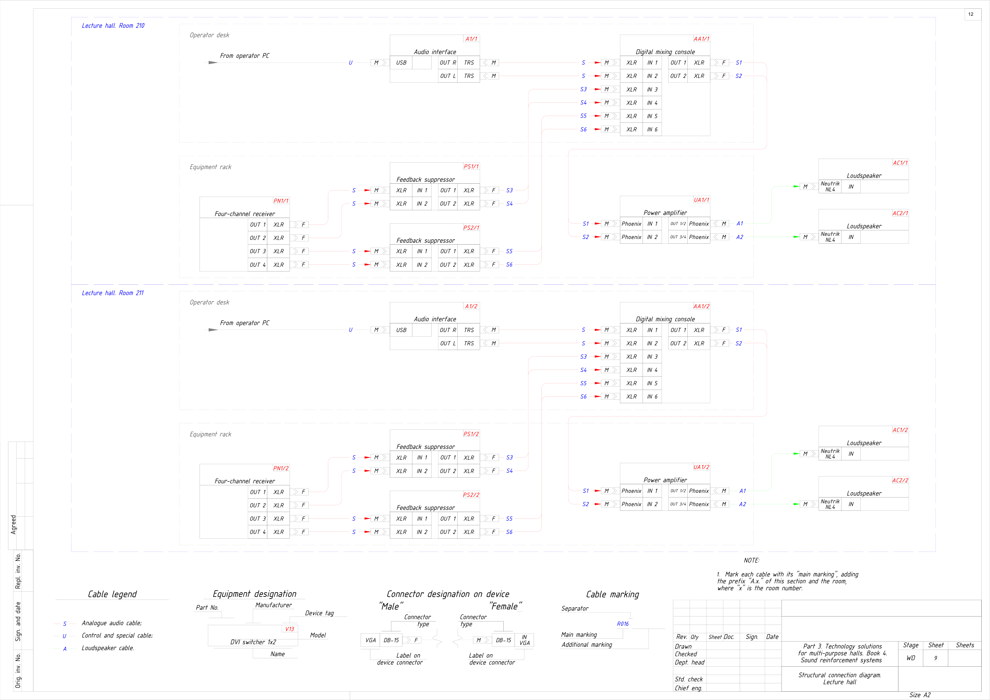
Two identical presentation halls of RC‑08: radio microphones through feedback suppressors, the presenter’s computer through a USB audio interface, a digital mixing console at the operator desk and a power amplifier driving the loudspeakers. Every cable is numbered for the cable schedule.

All 9 sheets of RC-08, PDF (303 KB)
Structural connection diagram, lecture halls: a working drawing of project RC-08 with device tags, connectors and numbered cables
Sheet 9 — Lecture hallsRC-08 · A2 · anonymised
14Reference complexes

Related complexes.

Documented project experience, separate from the reference designs above. Each project sheet records its own scope and outcome.

All complexes
15Talk to us

Share your meeting room brief.

Send room plans, seating, the meeting platform and guest connection needs.