Sheet 05 — Hotels, restaurants & clubs
Solution 05 · Hotels, restaurants & clubs

Set the room for the moment.

Give staff the controls they need for restaurant service, separate hotel events or a club performance. Plan sound, screens and the selected lighting functions around each space and the people who run it.

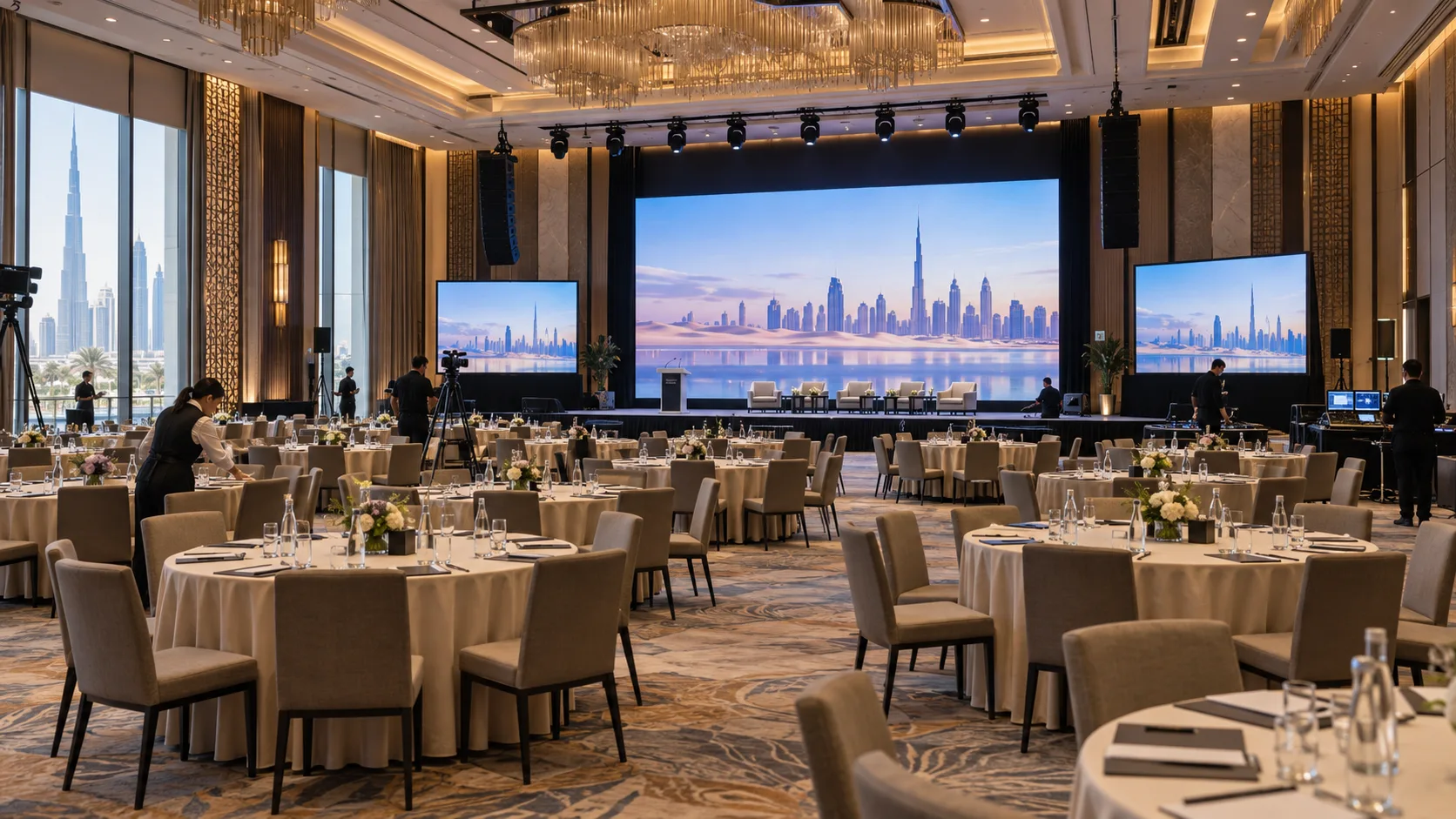
Concept visualisation of a Dubai hotel ballroom prepared with conference audiovisual systems
Fig. 05.0 — Hotels, restaurants & clubs
01Overview

Three operating tasks, three system designs.

A restaurant needs music that suits each zone and time of day. A hotel needs independent rooms that can become one event space. A club needs stage sound, video and lighting, while the lounge keeps its own programme and level.

We define the sources, zones, staff roles and guest connections before selecting equipment. Interior coordination, access for maintenance and installation windows form part of the design, including work in an operating hotel where phasing is agreed with the operator.

These three reference configurations describe intended functions and example quantities. They are starting points for project design, not fixed packages or evidence of completed installations. Final equipment, room coverage and integration behaviour require project selection and acceptance tests.

Explore meeting and conference rooms for two-way calls and digital signage for event listings and managed content.

02Where it is used08 environments

Real environments, real priorities.

Who works in each kind of space, what they work with and what matters most to them.

Application register
No.EnvironmentWho uses itWork and contentWhat matters mostTypical systems
A01Restaurants and barsF&B teamsDay and evening service, local announcementsIndependent sources and bounded volume by zoneHS-01: four indoor background audio zones
A02Divisible hotel function roomsBanquet team and event techniciansTwo simultaneous events or one combined eventCorrect audio, video and permissions in every partition stateHS-02: two rooms, A and B
A03Clubs and small performance spacesDJ, stage operator and duty managerDJ sets, spoken performances and programmed light scenesStage sound and visual operation with a separate loungeHS-03; performance requirements determine the final PA
A04Lobbies and pre-function areasFront office and events teamBackground music, announcements and event listingsZone control and a clear content workflowAdapt HS-01 audio; signage is separately specified
A05Hotel meeting and conference roomsGuests and hotel support teamPresentations and remote meetingsReadable content and a tested call workflowHS-02 covers presentation and room combining; cameras and conferencing need a separate room design
A06Pool decks and terracesF&B and engineering teamsOutdoor service and eventsEnvironmental suitability and sound spillExtend the zone design with equipment selected for the actual exposure; indoor speakers are not an outdoor specification
A07Spa and wellness areasSpa operationsQuiet background musicDiscreet coverage, local limits and moisture conditionsAdapt the background audio design and finishes to the room
A08Guest roomsGuests, hotel IT and TV service providerTV and private castingRoom isolation and supported interfacesSeparate TV/casting scope with the provider; not included in HS-01–03
03Typical configurations

Three starting points, compared.

Choose the workflow closest to your brief. Compare its scope, interfaces and operating limits before selecting equipment.

Compare all 3 configurations
Configuration

Restaurant audio zones

HS-01

Set music and announcement levels across four indoor zones. Reference design; integration and site tests required.

Explore HS-01

Divisible hotel rooms

HS-02

Run two separate presentations or one combined event. Reference design; every room mode must be tested.

Explore HS-02

Club stage & lounge

HS-03

Operate stage sound, LED and light while the lounge keeps its own music. Reference design; acoustic and production brief required.

Explore HS-03
Primary task

Background music and everyday announcements

Separate events or one combined event

DJ/performance sound, stage visuals and independent lounge music

Example scope

Four indoor zones

Two adjacent rooms with one movable partition

One stage area and one lounge

Programme sources

Two music players and one paging microphone

Two guest presentation inputs, two music players and four microphones

One guest DJ set, four microphones, one lounge player and one video player

Room sound

Sixteen ceiling speakers, four per zone

Sixteen ceiling speakers, eight per room

Two active tops and two active subwoofers; four lounge ceiling speakers

Video

Optional, separately specified

Two displays and one 4 × 2 matrix; two inputs reserved

One LED surface with processor and one player

Lighting

Outside base scope

Building lighting interface optional

One console, one isolated DMX splitter and twelve example fixtures

Control

Four zone panels and a scheduling controller

Two panels, a partition sensor, network contact interface and room-combine processor

Two staff panels, system controller and separate audio/video/light operator controls

Key limit

Background and speech duties; no stage PA

Ceiling sound for speech and modest background programme; no conferencing in the base design

PA coverage, sound spill, LED size and fixture selection remain project specific

Status

Reference design; integration and site tests required

Reference design; every room mode must be tested

Reference design; acoustic and production brief required

Restaurant audio zones

HS-01

Set music and announcement levels across four indoor zones. Reference design; integration and site tests required.

Explore HS-01
Primary task
Background music and everyday announcements
Example scope
Four indoor zones
Programme sources
Two music players and one paging microphone
Room sound
Sixteen ceiling speakers, four per zone
Video
Optional, separately specified
Lighting
Outside base scope
Control
Four zone panels and a scheduling controller
Key limit
Background and speech duties; no stage PA
Status
Reference design; integration and site tests required

Divisible hotel rooms

HS-02

Run two separate presentations or one combined event. Reference design; every room mode must be tested.

Explore HS-02
Primary task
Separate events or one combined event
Example scope
Two adjacent rooms with one movable partition
Programme sources
Two guest presentation inputs, two music players and four microphones
Room sound
Sixteen ceiling speakers, eight per room
Video
Two displays and one 4 × 2 matrix; two inputs reserved
Lighting
Building lighting interface optional
Control
Two panels, a partition sensor, network contact interface and room-combine processor
Key limit
Ceiling sound for speech and modest background programme; no conferencing in the base design
Status
Reference design; every room mode must be tested

Club stage & lounge

HS-03

Operate stage sound, LED and light while the lounge keeps its own music. Reference design; acoustic and production brief required.

Explore HS-03
Primary task
DJ/performance sound, stage visuals and independent lounge music
Example scope
One stage area and one lounge
Programme sources
One guest DJ set, four microphones, one lounge player and one video player
Room sound
Two active tops and two active subwoofers; four lounge ceiling speakers
Video
One LED surface with processor and one player
Lighting
One console, one isolated DMX splitter and twelve example fixtures
Control
Two staff panels, system controller and separate audio/video/light operator controls
Key limit
PA coverage, sound spill, LED size and fixture selection remain project specific
Status
Reference design; acoustic and production brief required

Reference configurations. Example quantities require project selection, compatibility checks and system acceptance tests.

Follow the signal path for your configuration.

HS-01

Restaurant audio zones

Reference design; integration and site tests required

Four indoor restaurant areas select from two shared music sources. Staff adjust only their own zone, choose day or evening settings and make an announcement to selected zones.

HS-01 · Restaurant audio zones

Two music players and a paging microphone feed four independent restaurant audio zones. Staff controls and the scheduling controller use separate control routes.

Signal flow

Signal flow. Devices, connections and conditions follow the drawing.Open SVG ↗
HS-01 · Signal flowTwo stereo players and one paging microphone feed four mono DSP mixes, four independent 100 V amplifier channels and sixteen ceiling speakers. Control commands and status are separate. This is not a certified voice alarm system. Shared once per restaurant rack, AC power, mounting, cables, licences 2 players allow 2 different programmes Reference quantities, not measured coverage Everyday paging and programme mute do not replace a certified voice alarm system Repeated device identifiers refer to the same equipment across views. Equipment illustrations are schematic; labels define quantities.{"sourceHash":"dbcd1c40ea6adbd661dbae4f1f96fe127715873b60ab5cf839f2c897f0cd6948","view":"signal","nodes":["BGM","DSP","MIC","AMP","SPK"],"edges":["L01","L02","L03","L04"]}PIXEL COMMAND SOLUTIONS / HS-01 / SIGNAL FLOWSignal flowREFERENCE DESIGN · PROJECT VALIDATION REQUIREDBGM → DSP: L/R × 2L/R × 2MIC → DSP: 1 balanced mic1 balanced micDSP → AMP: OUT1–4: four mono line feedsOUT1–4: four mono linefeedsAMP → SPK: 4 separate 100 V lines4 separate 100 V lines2 music players 4 analogue channelsBGM2 music players1 zone DSP 8 in / 8 out L/R summed internallyDSP1 zone DSP1 paging microphone set zone selection + talkMIC1 paging microphoneset1 four-channel amplifier 4 × 120 W / 100 VAMP1 four-channelamplifier16 ceiling speakers 4 zones × 4 speakers 6 W tap / 24 W per lineSPK16 ceiling speakersAudio
Devices, connections & design conditions 4 connections
  • Two music players and a paging microphone feed four independent restaurant audio zones. Staff controls and the scheduling controller use separate control routes.
  • HS-01 reference diagram showing five analogue inputs, four 100 V speaker lines, four wall controls and programme mute coordination.
BGM
2 music players 4 analogue channels
DSP
1 zone DSP 8 in / 8 out L/R summed internally
MIC
1 paging microphone set zone selection + talk
AMP
1 four-channel amplifier 4 × 120 W / 100 V
SPK
16 ceiling speakers 4 zones × 4 speakers 6 W tap / 24 W per line
  1. BGM → DSPL/R × 2
  2. MIC → DSP1 balanced mic
  3. DSP → AMPOUT1–4: four mono line feeds
  4. AMP → SPK4 separate 100 V lines

Shared once per restaurant rack, AC power, mounting, cables, licences 2 players allow 2 different programmes

Reference quantities, not measured coverage Everyday paging and programme mute do not replace a certified voice alarm system

Control & status

Signal flow. Devices, connections and conditions follow the drawing.Open SVG ↗
HS-01 · Control & statusTwo stereo players and one paging microphone feed four mono DSP mixes, four independent 100 V amplifier channels and sixteen ceiling speakers. Control commands and status are separate. This is not a certified voice alarm system. Shared once per restaurant rack, AC power, mounting, cables, licences 2 players allow 2 different programmes Reference quantities, not measured coverage Everyday paging and programme mute do not replace a certified voice alarm system Repeated device identifiers refer to the same equipment across views. Equipment illustrations are schematic; labels define quantities.{"sourceHash":"dbcd1c40ea6adbd661dbae4f1f96fe127715873b60ab5cf839f2c897f0cd6948","view":"control","nodes":["DSP","MIC","PAN","CTL","NET","FIRE","ISO"],"edges":["L05","L06","L07","L08","L09","L10","L11"]}PIXEL COMMAND SOLUTIONS / HS-01 / CONTROL & STATUSControl & statusREFERENCE DESIGN · PROJECT VALIDATION REQUIREDPAN ↔ CTL: IP commands / statusIP commands / statusNET → PAN: LAN + panel PoELAN + panel PoENET → CTL: control LANcontrol LANCTL ↔ DSP: UDP/IP commands / status driver to verifyUDP/IP commands /statusMIC → DSP: 4 zone contacts + PTT 5 GPIO inputs4 zone contacts + PTTFIRE → ISO: agreed contactagreed contactISO → DSP: GPIO input 6: programme mute includes pagingGPIO input 6: programmemute1 zone DSP 8 in / 8 out L/R summed internallyDSP1 zone DSP1 paging microphone set zone selection + talkMIC1 paging microphoneset4 staff panels one role per zonePAN4 staff panels1 controller day/evening schedule clock + permissionsCTL1 controller1 managed 16-port switch 10 ports assigned PoE budget ≥180 WNET1 managed 16-portswitch1 building signal interface external contractorFIRE1 building signalinterface1 isolation interface setISO1 isolation interfacesetControl / status
Devices, connections & design conditions 7 connections
  • Two music players and a paging microphone feed four independent restaurant audio zones. Staff controls and the scheduling controller use separate control routes.
  • HS-01 reference diagram showing five analogue inputs, four 100 V speaker lines, four wall controls and programme mute coordination.
DSP
1 zone DSP 8 in / 8 out L/R summed internally
MIC
1 paging microphone set zone selection + talk
PAN
4 staff panels one role per zone
CTL
1 controller day/evening schedule clock + permissions
NET
1 managed 16-port switch 10 ports assigned PoE budget ≥180 W
FIRE
1 building signal interface external contractor
ISO
1 isolation interface set
  1. PAN ↔ CTLIP commands / status
  2. NET → PANLAN + panel PoE
  3. NET → CTLcontrol LAN
  4. CTL ↔ DSPUDP/IP commands / status driver to verify
  5. MIC → DSP4 zone contacts + PTT 5 GPIO inputs
  6. FIRE → ISOagreed contact
  7. ISO → DSPGPIO input 6: programme mute includes paging

Shared once per restaurant rack, AC power, mounting, cables, licences 2 players allow 2 different programmes

Reference quantities, not measured coverage Everyday paging and programme mute do not replace a certified voice alarm system

Typical architecture · not a project drawing

Workflow, boundaries and intended result

Composition

Two stereo music players, one paging microphone with zone selection and talk control, one 8-input/8-output audio processor, one four-channel 100 V amplifier and sixteen ceiling loudspeakers. Four wall panels and one separate scheduling/control processor provide the operating interface. A managed control switch, power, cabling and installation materials are counted once for the restaurant.

Architecture

The players occupy four analogue input channels; the microphone uses one. Stereo sources are summed inside the processor, which creates four independent mono zone outputs. Each output feeds its own amplifier channel and four loudspeakers. At an illustrative 6 W tap per speaker, each line carries 24 W. This is an electrical load calculation, not a coverage measurement.

Boundaries

Two players allow two different music programmes at once; four zones do not create four independent streams. Announcements lower or mute music only in the selected zones, then restore the agreed setting. Screens, outdoor speakers and stage sound are additional scope. Staff controls and scheduling require a documented, tested device interface.

Intended result

Staff can run day and evening service, make a local announcement and keep other zones at their own settings.

Example equipment for HS-01

Example quantities for the selected configuration; final selection follows the approved design. A catalogue listing does not confirm stock, delivery time or complete-system compatibility.

Background music players
2

Audio sources

Microphone channels
1 paging

Microphones; wireless substitution by RF brief

Zone / room-combine processor
1

Audio processors · Network audio

Four-channel 100 V amplifier
1; four channels used

Amplifiers

Ceiling loudspeakers
16

Loudspeakers

Staff panels / separate controller
4 / 1

Select with control API, status and power requirements

Guest presentation connections / displays
Optional

Display type and transport by room design

Shared installation infrastructure
One set per restaurant

Control network, power, racks, mounting, cabling and licences scheduled separately

HS-02

Divisible hotel rooms

Reference design; every room mode must be tested

Rooms A and B host different presentations with the partition closed. With the partition open and an authorised operator's confirmation, they share one presentation and a combined microphone mix.

HS-02 · Divisible hotel rooms

Independent video outputs and audio mixes follow the approved A/B/A+B room mode. The partition sensor connects through a network contact interface.

Signal flow

Signal flow. Devices, connections and conditions follow the drawing.Open SVG ↗
HS-02 · Signal flowTwo guest HDMI inputs feed a four by two matrix. Each output has a stereo extractor and display. Four microphones, four presentation channels and four music channels feed the room processor. A network contact interface connects the partition sensor. Audio and video modes require operator confirmation. Shared once per room pair rack, AC power, mounting, cables, control licences Alternative: built-in dual audio extraction replaces both extractors A+B: one programme feed, selected microphone mix Do not sum EX-A and EX-B when carrying the same source Unknown partition: block automatic combine and show fault AV programme mute is not certified voice alarm Repeated device identifiers refer to the same equipment across views. Equipment illustrations are schematic; labels define quantities.{"sourceHash":"067e98a0eefba6ac5b92bac97f81b2fb9619c443bda81eedd6b155628b6d98ea","view":"signal","nodes":["GUEST","MAT","EX","DISP","MIC","CORE","BGM","AMP","SPK"],"edges":["L01","L02","L03","L04","L05","L06","L07","L08"]}PIXEL COMMAND SOLUTIONS / HS-02 / SIGNAL FLOWSignal flowREFERENCE DESIGN · PROJECT VALIDATION REQUIREDGUEST → MAT: HDMI IN1 / IN2 IN3 / IN4 reservedHDMI · IN1 /IN2MAT → EX: OUT A / OUT BOUT A / OUT BEX → DISP: 2 HDMI pass-through paths2 × HDMIMIC → CORE: 4 balanced feeds4 balancedfeedsBGM → CORE: 4 analogue L/R channels4 analogue channelsCORE → AMP: OUT1 = A / OUT2 = B balanced lineOUT1 A / OUT2 BAMP → SPK: 2 electrically separate lines2 separate linesEX → CORE: EX-A L/R + EX-B L/R 4 analogue channels4 analogue channels2 guest sources A and B / customer devicesGUEST2 guest sources1 HDMI matrix 4 × 2MAT1 HDMI matrix2 stereo audio extractors one per matrix outputEX2 stereo audioextractors2 displays A and B internal speakers offDISP2 displays4 microphone channels A1/A2 and B1/B2MIC4 microphone channels1 room-combine processor 12 inputs / 2 mono outputs used A / B / separate / A+BCORE1 room-combineprocessor2 background playersBGM2 background players1 four-channel 100 V amplifier CH1 / CH2 used CH3 / CH4 spareAMP1 four-channel 100 Vamplifier16 ceiling speakers 8 per room × 6 W 48 W on each lineSPK16 ceiling speakersVideo / LED dataAudio
Devices, connections & design conditions 8 connections
  • Independent video outputs and audio mixes follow the approved A/B/A+B room mode. The partition sensor connects through a network contact interface.
  • HS-02 reference diagram showing two displays, output audio extraction, room audio processing, separate 100 V lines and confirmed mode feedback.
GUEST
2 guest sources A and B / customer devices
MAT
1 HDMI matrix 4 × 2
EX
2 stereo audio extractors one per matrix output
DISP
2 displays A and B internal speakers off
MIC
4 microphone channels A1/A2 and B1/B2
CORE
1 room-combine processor 12 inputs / 2 mono outputs used A / B / separate / A+B
BGM
2 background players
AMP
1 four-channel 100 V amplifier CH1 / CH2 used CH3 / CH4 spare
SPK
16 ceiling speakers 8 per room × 6 W 48 W on each line
  1. GUEST → MATHDMI IN1 / IN2 IN3 / IN4 reserved
  2. MAT → EXOUT A / OUT B
  3. EX → DISP2 HDMI pass-through paths
  4. MIC → CORE4 balanced feeds
  5. BGM → CORE4 analogue L/R channels
  6. CORE → AMPOUT1 = A / OUT2 = B balanced line
  7. AMP → SPK2 electrically separate lines
  8. EX → COREEX-A L/R + EX-B L/R 4 analogue channels

Shared once per room pair rack, AC power, mounting, cables, control licences Alternative: built-in dual audio extraction replaces both extractors

A+B: one programme feed, selected microphone mix Do not sum EX-A and EX-B when carrying the same source Unknown partition: block automatic combine and show fault AV programme mute is not certified voice alarm

Control & status

Signal flow. Devices, connections and conditions follow the drawing.Open SVG ↗
HS-02 · Control & statusTwo guest HDMI inputs feed a four by two matrix. Each output has a stereo extractor and display. Four microphones, four presentation channels and four music channels feed the room processor. A network contact interface connects the partition sensor. Audio and video modes require operator confirmation. Shared once per room pair rack, AC power, mounting, cables, control licences Alternative: built-in dual audio extraction replaces both extractors A+B: one programme feed, selected microphone mix Do not sum EX-A and EX-B when carrying the same source Unknown partition: block automatic combine and show fault AV programme mute is not certified voice alarm Repeated device identifiers refer to the same equipment across views. Equipment illustrations are schematic; labels define quantities.{"sourceHash":"067e98a0eefba6ac5b92bac97f81b2fb9619c443bda81eedd6b155628b6d98ea","view":"control","nodes":["MAT","DISP","CORE","SENSOR","GPIO","FIRE","ISO","PAN","NET"],"edges":["L09","L10","L11","L12","L13","L14","L15","L16","L17"]}PIXEL COMMAND SOLUTIONS / HS-02 / CONTROL & STATUSControl & statusREFERENCE DESIGN · PROJECT VALIDATION REQUIREDSENSOR → GPIO: 2 contact inputs2 contact inputsFIRE → ISO: agreed contactagreed contactISO → GPIO: third input: programme mutethird input: programmemuteNET → GPIO: LAN / PoELAN / PoENET → PAN: LAN / PoELAN / PoEGPIO → CORE: IP: position + mute + link status no direct GPIO on chosen processor v2IP: position + mute +link statusPAN ↔ CORE: IP commands / confirmed modeIP commands / confirmedmodeCORE ↔ MAT: IP route command / actual routeIP route command /actual routeCORE ↔ DISP: IP power command / statusIP power command /status1 HDMI matrix 4 × 2MAT1 HDMI matrix2 displays A and B internal speakers offDISP2 displays1 room-combine processor 12 inputs / 2 mono outputs used A / B / separate / A+BCORE1 room-combineprocessor1 partition sensor assembly open + closed contactsSENSOR1 partition sensorassembly1 network contact interface 3 inputs used PoE Type 1 Class 3GPIO1 network contactinterface1 building signal interface external contractorFIRE1 building signalinterface1 isolation interface setISO1 isolation interfaceset2 room panels local roles / combined masterPAN2 room panels1 managed 16-port switch 11 ports assigned PoE budget ≥120 WNET1 managed 16-portswitchControl / status
Devices, connections & design conditions 9 connections
  • Independent video outputs and audio mixes follow the approved A/B/A+B room mode. The partition sensor connects through a network contact interface.
  • HS-02 reference diagram showing two displays, output audio extraction, room audio processing, separate 100 V lines and confirmed mode feedback.
MAT
1 HDMI matrix 4 × 2
DISP
2 displays A and B internal speakers off
CORE
1 room-combine processor 12 inputs / 2 mono outputs used A / B / separate / A+B
SENSOR
1 partition sensor assembly open + closed contacts
GPIO
1 network contact interface 3 inputs used PoE Type 1 Class 3
FIRE
1 building signal interface external contractor
ISO
1 isolation interface set
PAN
2 room panels local roles / combined master
NET
1 managed 16-port switch 11 ports assigned PoE budget ≥120 W
  1. SENSOR → GPIO2 contact inputs
  2. FIRE → ISOagreed contact
  3. ISO → GPIOthird input: programme mute
  4. NET → GPIOLAN / PoE
  5. NET → PANLAN / PoE
  6. GPIO → COREIP: position + mute + link status no direct GPIO on chosen processor v2
  7. PAN ↔ COREIP commands / confirmed mode
  8. CORE ↔ MATIP route command / actual route
  9. CORE ↔ DISPIP power command / status

Shared once per room pair rack, AC power, mounting, cables, control licences Alternative: built-in dual audio extraction replaces both extractors

A+B: one programme feed, selected microphone mix Do not sum EX-A and EX-B when carrying the same source Unknown partition: block automatic combine and show fault AV programme mute is not certified voice alarm

Typical architecture · not a project drawing

Workflow, boundaries and intended result

Composition

Two guest presentation connections, two displays, a 4 × 2 video matrix, two output audio extractors, two music players and four microphone channels, two per room. One room-combine audio/control processor, one four-channel 100 V amplifier and sixteen ceiling loudspeakers serve the two rooms. Two staff panels, one partition sensor assembly and a separate network contact interface handle operation and partition status. The two extractors are omitted if the selected matrix already provides the required two independent stereo audio outputs.

Architecture

Each display output has its own extracted stereo audio feed to the audio processor. Four microphones, four presentation audio channels and four music channels require twelve analogue inputs. Separate mono outputs feed amplifier channels A and B; the other two amplifier channels are unused in the reference design. Each room has eight speakers at an illustrative 6 W tap: 48 W per line. Combining rooms changes the signal routing; the two 100 V lines remain electrically separate.

Boundaries

The sensor reports position; it does not authorise an unexpected event change. Unknown position blocks automatic combining, and the interface shows a fault. Video routing and display status must be checked before indicating a completed mode change. A room-combine function does not merge two conferencing calls. Cameras, recording, hearing assistance, stage PA and additional production inputs are specified separately when required.

Intended result

The banquet team can prepare separate or combined events with matching picture, sound and controls, using a documented room-mode procedure.

Operating modes
ModeVideoAudioStaff control
A onlyA selects its source; B is blanked or offA microphones and selected programme in A; B mutedA controls A; B cannot change A
B onlyB selects its source; A is blanked or offB microphones and selected programme in B; A mutedB controls B; A cannot change B
A and B separatelyIndependent sources on the two screensEach room hears only its own microphones and selected programmeLocal panels control their own room
A+B combinedThe chosen source reaches both screensOne programme feed plus the selected microphone mix reaches both roomsAn authorised master controls the combined event; both panels show the confirmed mode
Example equipment for HS-02

Example quantities for the selected configuration; final selection follows the approved design. A catalogue listing does not confirm stock, delivery time or complete-system compatibility.

Background music players
2

Audio sources

Microphone channels
4; two per room

Microphones; wireless substitution by RF brief

Zone / room-combine processor
1

Audio processors · Network audio

Four-channel 100 V amplifier
1; two channels used

Amplifiers

Ceiling loudspeakers
16

Loudspeakers

Staff panels / separate controller
2 / processor-integrated

Select with control API, status and power requirements

Partition sensor / network contact interface
1 / 1

Select for position inputs, isolation and processor support

Guest presentation connections / displays
2 / 2

Display type and transport by room design

Video matrix / stereo audio extractors
1 / 2, or equivalent built-in extraction

Video matrices

Active tops / active subwoofers
Optional redesign

Selected by acoustic design

Shared installation infrastructure
One set per room pair

Control network, power, racks, mounting, cabling and licences scheduled separately

HS-03

Club stage & lounge

Reference design; acoustic and production brief required

An operator runs a DJ set or spoken performance with stage video and lighting. Lounge music remains on its own source and volume setting.

HS-03 · Club stage & lounge

Stage PA, lounge audio, LED video and DMX lighting have distinct signal paths and operating responsibilities.

Video & data

Signal flow. Devices, connections and conditions follow the drawing.Open SVG ↗
HS-03 · Video & dataStage mixer and speaker processing feed two active tops and two active subs with individual AC power. The lounge has its own source, DSP and 100 V amplifier. An HDMI player feeds an LED processor and surface. A lighting console feeds three isolated DMX branches with twelve fixtures. Staff controls and building programme mute are separate routes. 3 end terminators one per active branch DMX is one-way here cue state is not fixture telemetry each fixture also requires AC power Shared: rack, signal cables, power, mounting and licences 4 separate PA AC feeds + 12 lighting feeds + LED power by design No external power amplifier for active PA Stage monitors are an option; add aux feeds, AC and mute coverage Reference quantities, not a coverage or capacity guarantee No automatic timecode show or fixture feedback in this baseline AV programme mute does not replace certified voice alarm Repeated device identifiers refer to the same equipment across views. Equipment illustrations are schematic; labels define quantities.{"sourceHash":"7dfb309789fbbb468a6fcca8050fb9cc603e1590b046b0c76ebe6b6e987d9305","view":"signal","nodes":["PLAYER","LEDP","LED"],"edges":["L10","L11"]}PIXEL COMMAND SOLUTIONS / HS-03 / VIDEO & DATAVideo & dataREFERENCE DESIGN · PROJECT VALIDATION REQUIREDPLAYER → LEDP: HDMIHDMILEDP → LED: matched LED data links not a general LAN switchmatched LED data links1 video player silent visuals in base scopePLAYER1 video player1 LED processorLEDP1 LED processor1 LED surface cabinets + receiver cards count by geometryLED1 LED surfaceVideo / LED data
Devices, connections & design conditions 2 connections
  • Stage PA, lounge audio, LED video and DMX lighting have distinct signal paths and operating responsibilities.
  • HS-03 reference diagram showing active stage speakers with individual power, independent lounge sound, LED data and isolated lighting branches.
PLAYER
1 video player silent visuals in base scope
LEDP
1 LED processor
LED
1 LED surface cabinets + receiver cards count by geometry
  1. PLAYER → LEDPHDMI
  2. LEDP → LEDmatched LED data links not a general LAN switch

3 end terminators one per active branch

DMX is one-way here cue state is not fixture telemetry each fixture also requires AC power

Shared: rack, signal cables, power, mounting and licences 4 separate PA AC feeds + 12 lighting feeds + LED power by design No external power amplifier for active PA Stage monitors are an option; add aux feeds, AC and mute coverage

Reference quantities, not a coverage or capacity guarantee No automatic timecode show or fixture feedback in this baseline AV programme mute does not replace certified voice alarm

Audio & return paths

Signal flow. Devices, connections and conditions follow the drawing.Open SVG ↗
HS-03 · Audio & return pathsStage mixer and speaker processing feed two active tops and two active subs with individual AC power. The lounge has its own source, DSP and 100 V amplifier. An HDMI player feeds an LED processor and surface. A lighting console feeds three isolated DMX branches with twelve fixtures. Staff controls and building programme mute are separate routes. 3 end terminators one per active branch DMX is one-way here cue state is not fixture telemetry each fixture also requires AC power Shared: rack, signal cables, power, mounting and licences 4 separate PA AC feeds + 12 lighting feeds + LED power by design No external power amplifier for active PA Stage monitors are an option; add aux feeds, AC and mute coverage Reference quantities, not a coverage or capacity guarantee No automatic timecode show or fixture feedback in this baseline AV programme mute does not replace certified voice alarm Repeated device identifiers refer to the same equipment across views. Equipment illustrations are schematic; labels define quantities.{"sourceHash":"7dfb309789fbbb468a6fcca8050fb9cc603e1590b046b0c76ebe6b6e987d9305","view":"audio","nodes":["DJ","DI","MIX","MIC","PROC","TOP","SUB","BGM","DSP","AMP","SPK"],"edges":["L01","L02","L03","L04","L05","L06","L07","L08","L09"]}PIXEL COMMAND SOLUTIONS / HS-03 / AUDIO & RETURN PATHSAudio & return pathsREFERENCE DESIGN · PROJECT VALIDATION REQUIREDDJ → DI: stereo linestereo lineDI → MIX: CH1/2CH1/2MIC → MIX: CH3–6CH3–6MIX → PROC: balanced L/Rbalanced L/RPROC → TOP: OUT1/2: line L/ROUT1/2: line L/RPROC → SUB: OUT3/4: lineOUT3/4: lineBGM → DSP: analogue L/Ranalogue L/RDSP → AMP: mono linemono lineAMP → SPK: 1 independent 100 V line1 independent 100 Vline1 guest DJ setDJ1 guest DJ set1 stereo line isolationDI1 stereo lineisolation1 stage mixer 6 of ≥8 inputs usedMIX1 stage mixer4 wired microphone channelsMIC4 wired microphonechannels1 speaker processor 2 inputs / ≥4 outputs limits, filters, delays, mutePROC1 speaker processor2 active tops each: signal + ACTOP2 active tops2 active subwoofers each: signal + ACSUB2 active subwoofers1 music playerBGM1 music player1 zone DSP 2 inputs / 1 output usedDSP1 zone DSP1 four-channel 100 V amplifier CH1 used; CH2–4 spareAMP1 four-channel 100 Vamplifier4 ceiling speakers 6 W tap / 24 W lineSPK4 ceiling speakersAudio
Devices, connections & design conditions 9 connections
  • Stage PA, lounge audio, LED video and DMX lighting have distinct signal paths and operating responsibilities.
  • HS-03 reference diagram showing active stage speakers with individual power, independent lounge sound, LED data and isolated lighting branches.
DJ
1 guest DJ set
DI
1 stereo line isolation
MIX
1 stage mixer 6 of ≥8 inputs used
MIC
4 wired microphone channels
PROC
1 speaker processor 2 inputs / ≥4 outputs limits, filters, delays, mute
TOP
2 active tops each: signal + AC
SUB
2 active subwoofers each: signal + AC
BGM
1 music player
DSP
1 zone DSP 2 inputs / 1 output used
AMP
1 four-channel 100 V amplifier CH1 used; CH2–4 spare
SPK
4 ceiling speakers 6 W tap / 24 W line
  1. DJ → DIstereo line
  2. DI → MIXCH1/2
  3. MIC → MIXCH3–6
  4. MIX → PROCbalanced L/R
  5. PROC → TOPOUT1/2: line L/R
  6. PROC → SUBOUT3/4: line
  7. BGM → DSPanalogue L/R
  8. DSP → AMPmono line
  9. AMP → SPK1 independent 100 V line

3 end terminators one per active branch

DMX is one-way here cue state is not fixture telemetry each fixture also requires AC power

Shared: rack, signal cables, power, mounting and licences 4 separate PA AC feeds + 12 lighting feeds + LED power by design No external power amplifier for active PA Stage monitors are an option; add aux feeds, AC and mute coverage

Reference quantities, not a coverage or capacity guarantee No automatic timecode show or fixture feedback in this baseline AV programme mute does not replace certified voice alarm

Control & status

Signal flow. Devices, connections and conditions follow the drawing.Open SVG ↗
HS-03 · Control & statusStage mixer and speaker processing feed two active tops and two active subs with individual AC power. The lounge has its own source, DSP and 100 V amplifier. An HDMI player feeds an LED processor and surface. A lighting console feeds three isolated DMX branches with twelve fixtures. Staff controls and building programme mute are separate routes. 3 end terminators one per active branch DMX is one-way here cue state is not fixture telemetry each fixture also requires AC power Shared: rack, signal cables, power, mounting and licences 4 separate PA AC feeds + 12 lighting feeds + LED power by design No external power amplifier for active PA Stage monitors are an option; add aux feeds, AC and mute coverage Reference quantities, not a coverage or capacity guarantee No automatic timecode show or fixture feedback in this baseline AV programme mute does not replace certified voice alarm Repeated device identifiers refer to the same equipment across views. Equipment illustrations are schematic; labels define quantities.{"sourceHash":"7dfb309789fbbb468a6fcca8050fb9cc603e1590b046b0c76ebe6b6e987d9305","view":"control","nodes":["PROC","DSP","LEDP","LIGHT","SPLIT","WASH","MOVE","PAN","CTL","NET","FIRE","ISO"],"edges":["L12","L13","L14","L15","L16","L17","L18","L19","L20","L21","L22","L23"]}PIXEL COMMAND SOLUTIONS / HS-03 / CONTROL & STATUSControl & statusREFERENCE DESIGN · PROJECT VALIDATION REQUIREDLIGHT → SPLIT: DMXDMXSPLIT → WASH: branches 1/2 addresses 1–64Branches 1/2· 1–64SPLIT → MOVE: branch 3 addresses 65–128Branch 3 · 65–128PAN ↔ CTL: IP commands / statusIP commands / statusNET → PAN: LAN / panel PoELAN / panelPoEFIRE → ISO: agreed contactAgreedcontactCTL ↔ DSP: IP source / gain / status driver to verifyIP source / gain /statusCTL ↔ PROC: IP agreed preset / status interface to verifyIP preset /statusCTL ↔ LEDP: IP agreed commands / statusIP commands / statusCTL ↔ LIGHT: IP cue commands / console state if supported by selected consoleIP cue / console state· if supportedISO → PROC: contact: all stage outputs muteContact: all stageoutputs muteISO → DSP: contact: lounge muteContact: lounge mute1 speaker processor 2 inputs / ≥4 outputs limits, filters, delays, mutePROC1 speaker processor1 zone DSP 2 inputs / 1 output usedDSP1 zone DSP1 LED processorLEDP1 LED processor1 lighting console ≥1 DMX universeLIGHT1 lighting console1 isolated splitter ≥4 outputs; 3 usedSPLIT1 isolated splitter8 wash fixtures ≤8 slots eachWASH8 wash fixtures4 moving fixtures ≤16 slots eachMOVE4 moving fixtures2 staff panels lounge and duty managerPAN2 staff panels1 system controller permissions + agreed presetsCTL1 system controller1 managed 16-port switch 12 ports assigned / reserved PoE budget ≥120 WNET1 managed 16-portswitch1 building signal interface external contractorFIRE1 building signalinterface1 isolation interface set two programme mute pathsISO1 isolation interfacesetControl / status
Devices, connections & design conditions 12 connections
  • Stage PA, lounge audio, LED video and DMX lighting have distinct signal paths and operating responsibilities.
  • HS-03 reference diagram showing active stage speakers with individual power, independent lounge sound, LED data and isolated lighting branches.
PROC
1 speaker processor 2 inputs / ≥4 outputs limits, filters, delays, mute
DSP
1 zone DSP 2 inputs / 1 output used
LEDP
1 LED processor
LIGHT
1 lighting console ≥1 DMX universe
SPLIT
1 isolated splitter ≥4 outputs; 3 used
WASH
8 wash fixtures ≤8 slots each
MOVE
4 moving fixtures ≤16 slots each
PAN
2 staff panels lounge and duty manager
CTL
1 system controller permissions + agreed presets
NET
1 managed 16-port switch 12 ports assigned / reserved PoE budget ≥120 W
FIRE
1 building signal interface external contractor
ISO
1 isolation interface set two programme mute paths
  1. LIGHT → SPLITDMX
  2. SPLIT → WASHbranches 1/2 addresses 1–64
  3. SPLIT → MOVEbranch 3 addresses 65–128
  4. PAN ↔ CTLIP commands / status
  5. NET → PANLAN / panel PoE
  6. FIRE → ISOagreed contact
  7. CTL ↔ DSPIP source / gain / status driver to verify
  8. CTL ↔ PROCIP agreed preset / status interface to verify
  9. CTL ↔ LEDPIP agreed commands / status
  10. CTL ↔ LIGHTIP cue commands / console state if supported by selected console
  11. ISO → PROCcontact: all stage outputs mute
  12. ISO → DSPcontact: lounge mute

3 end terminators one per active branch

DMX is one-way here cue state is not fixture telemetry each fixture also requires AC power

Shared: rack, signal cables, power, mounting and licences 4 separate PA AC feeds + 12 lighting feeds + LED power by design No external power amplifier for active PA Stage monitors are an option; add aux feeds, AC and mute coverage

Reference quantities, not a coverage or capacity guarantee No automatic timecode show or fixture feedback in this baseline AV programme mute does not replace certified voice alarm

Typical architecture · not a project drawing

Workflow, boundaries and intended result

Composition

One guest DJ set, one stereo line isolation interface, four wired microphone channels, a stage mixer and a speaker processor feed two active tops and two active subwoofers. The active speakers each need a line-level signal and their own power feed; they have no separate external power amplifier. One music player, a zone processor, one 100 V amplifier and four ceiling speakers serve the lounge. One media player, one LED processor and one LED surface provide visuals. One lighting console, one isolated splitter, eight example wash fixtures and four example moving fixtures provide the starting lighting layout. Two staff panels and one system controller manage agreed presets and permissions.

Architecture

Stereo stage audio reaches the speaker processor, which provides four separate line outputs for the tops and subs. Lounge audio uses a separate mono output and 100 V line, with a 24 W reference speaker load. Video travels over HDMI to the LED processor, then over the selected LED system's data links to its receiver cards. The lighting console feeds the fixtures through isolated DMX branches.

Boundaries

Two tops and two subs are an initial arrangement, not a capacity or sound-level guarantee. Coverage, low-frequency spill and isolation from neighbouring rooms require an acoustic design. The base scope has no stage monitors; performers needing them require the separately listed monitor option and additional mix outputs. LED dimensions, resolution and power follow the actual surface. Lighting quantities are a layout assumption, with fixture modes and addresses agreed during design. Timecode shows, automatic audio/video synchronisation, recording and broadcast are outside the baseline.

Intended result

Technical staff can change between DJ and microphone-led operation, play stage visuals, recall tested lighting scenes and keep lounge settings independent.

Example equipment for HS-03

Example quantities for the selected configuration; final selection follows the approved design. A catalogue listing does not confirm stock, delivery time or complete-system compatibility.

Background music players
1 for lounge

Audio sources

Microphone channels
4 wired

Microphones; wireless substitution by RF brief

Zone / room-combine processor
1 for lounge

Audio processors · Network audio

Four-channel 100 V amplifier
1; one channel used

Amplifiers

Ceiling loudspeakers
4 in lounge

Loudspeakers

Staff panels / separate controller
2 / 1

Select with control API, status and power requirements

Guest presentation connections / displays
Separate LED workflow

Display type and transport by room design

DJ set / stereo line isolation / stage mixer / speaker processor
1 / 1 / 1 / 1

Guest DJ set; audio processing by interfaces

Active tops / active subwoofers
2 / 2

Selected by acoustic design

Video player / LED processor / LED surface
1 / 1 / 1 set

LED equipment

Lighting console / isolated splitter
1 / 1

Lighting controls

Wash / moving fixtures
8 / 4 example positions

Lighting equipment

Shared installation infrastructure
One set per club

Control network, power, racks, mounting, cabling and licences scheduled separately

05Reference architectureInteractive

How a typical system fits together.

Four layers, from the sources to the people operating the system. Select a layer to see its components and the interfaces between them.

Typical architecture · Hotels, restaurants & clubs

L2 · Selected layerProcessing & transport

How signals are routed and processed in a typical system of this kind.

Components and interfaces
  • Zoned DSP and 100 V amplificationHDMI / AudioStage signals go to active PA at line level; a 100 V output must never feed an active speaker input
  • Video matrix and extractionHDMI / AudioStage signals go to active PA at line level; a 100 V output must never feed an active speaker input
  • Stage speaker processingHDMI / AudioStage signals go to active PA at line level; a 100 V output must never feed an active speaker input
  • LED processingHDMI / AudioStage signals go to active PA at line level; a 100 V output must never feed an active speaker input
  • DMX distributionHDMI / AudioStage signals go to active PA at line level; a 100 V output must never feed an active speaker input
Documented scope · Hotels, restaurants & clubs
  • Zoned background music, everyday announcements and staff controls.
  • Divisible hotel rooms with coordinated audio, presentation video and operating permissions.
  • Guest presentation and production connections with defined signal levels.
  • Club stage sound, LED video and operated lighting, with a separate lounge audio zone.
  • Interfaces to hotel networks, signage and building systems where specified.
  • Drawings, configuration backups, acceptance records and training for each staff role.
Prepare for the first conversation
  1. 01Plans, sections, ceiling heights, zone names and partition positions.
  2. 02Day/evening routines, event types, layouts and simultaneous source requirements.
  3. 03Existing sound, screens, controls, cabling and hotel technology standards.
  4. 04Guest/DJ connections, sample presentation and video content, and typical technical riders.
  5. 05Acoustic information, neighbouring uses, level limits and outdoor exposure where relevant.
  6. 06Staff roles, panel locations, required languages and accessibility needs.
  7. 07IT, power, mounting, fire alarm and building-system interface contacts.
  8. 08Installation windows, maintenance access, budget brief and project contact.
Share your venue plans
06Design parametersTypical guidance · confirmed per project

What the design has to get right.

The engineering checks behind every drawing. Rules of thumb are starting points; the project values are confirmed with the people named.

Design parameters
No.ParameterGuidanceRule of thumbConfirmed with
D01Zone boundariesService areas, sources and staff responsibilitiesOne controlled mix per independent zone; count simultaneous programmes separatelyF&B and operations
D02Loudspeaker loadingTransformer taps, cable lengths and lossesSum the selected taps on each 100 V channel and document the amplifier marginAV designer and installer
D03Sound coverageCeiling height, finishes, background noise and event layoutsPredict coverage and measure against agreed project targetsAcoustic designer and operator
D04Divisible roomsPartition positions, simultaneous events and operator rightsTest A, B, separate A/B and combined A+B, including fault recoveryBanquet and engineering teams
D05Screens and LEDActual content, viewing positions, light and service accessSelect screen size and pixel mapping for the approved layoutEvents team and interior designer
D06Guest connectionsSource format, connector, level and cable distanceLabel each tie-in and test the agreed guest equipmentEvent technicians
D07Stage soundProgramme, low-frequency demand and neighbouring roomsChoose PA and level limits from the acoustic briefVenue operator and acoustic designer
D08LightingFixture placement, modes, addresses and cuesIssue a patch and test each scene and loss-of-data behaviourLighting operator and fit-out team
D09Staff operationLocal volume limits, scene access and device feedbackSeparate staff and technical functions; expose unresolved faultsEach operating team
D10Building and accessibility interfacesProgramme mute, hearing assistance, environment and accessAgree interfaces and acceptance responsibilities before orderingResponsible building specialists
D11Power and mountingEvery active device, LED and lighting circuit, structural loadsUse nameplate data and approved mounting details; retain maintenance accessElectrical and structural designers
D12Hotel constraintsOperator technology standards, existing systems and access windowsConfirm deviations and phased work before installationHotel operator and contractor
Common mistakes

And how the design process prevents them.

  1. M01

    Mistake: Four zones need four different playlists but only two players are provided.

    Prevention: Count simultaneous programmes during scoping.

  2. M02

    Mistake: A speaker count is mistaken for sound coverage.

    Prevention: Calculate the electrical load and the acoustic coverage separately.

  3. M03

    Mistake: The combined room plays the same presentation audio twice.

    Prevention: Select one extracted programme feed for A+B and distribute that mix to both room outputs.

  4. M04

    Mistake: A partition contact changes while an event is running.

    Prevention: Show the requested state and require authorised confirmation; retain a defined fault procedure.

  5. M05

    Mistake: A guest mixer bypasses house sound limits or programme mute.

    Prevention: Route the agreed tie-in through house processing and test the complete path.

  6. M06

    Mistake: A lighting cue or device command is shown as confirmed without feedback.

    Prevention: Display acknowledged state where supported and require a visual check where it is not.

07Design referencesEditions checked per project

The references we design to.

Equipment documentation, industry guides and project requirements inform the design. Confirm applicable editions and acceptance criteria for the site.

Equipment documentation and industry guides03

  • ANSI/AVIXA A102.01Audio Coverage UniformityDefine and measure the listening areaCheck current edition
  • ANSI/AVIXA V202.01Display Image Size for 2D ContentSize presentation displays and check viewing positionsCheck current edition
  • ANSI/AVIXA D402.02AV Systems Performance VerificationAgree verification criteria and report resultsCheck current edition

Local and project requirements01

  • Project requirements and applicable local rulesProject design referenceElectrical works, mounting, access, radio equipment, accessibility and building interfacesCheck current edition
08Integrations08 interfaces

Connected to the building and its IT.

The systems this solution usually exchanges signals or data with, and why. Each interface is agreed with the system owner.

  • I01

    Music services

    Player analogue output and documented service access

    Content rights, subscriptions and recovery from a lost service are agreed with the operator

  • I02

    Partition system

    Position contacts through the specified network contact interface

    HS-02: report position; authorised room-mode logic controls audio and video

  • I03

    Visiting production

    Labelled balanced audio and agreed video inputs

    Define house processing, levels and programme mute; additional PA or broadcast routes are separate scope

  • I04

    Hotel IT

    Managed control network and agreed internet access

    Keep device control separate from guest access; specify addressing, power and support ownership

  • I05

    Signage and event booking

    Documented export/API to the selected signage service

    Optional event listings with reviewed templates and manual fallback; no booking connector is assumed

  • I06

    Building and lighting controls

    Documented IP/serial interface or isolated contacts

    Optional building presets and status; stage DMX operation remains with the lighting console

  • I07

    Fire alarm interface

    Agreed isolated signal from the responsible contractor

    Mute programme audio, including agreed guest feeds; this AV function does not replace a certified voice alarm system

  • I08

    Hearing assistance / TV and casting

    Specified audio feed / provider-supported connection

    Separate project scope, including room isolation, commissioning and accessibility checks

10Delivery

From the brief to an accepted system.

The six stages follow the selected configuration. Platform development or unconfirmed software functions require their own agreed scope and validation milestones.

Our services
  1. Stage 01

    Scope and architecture

    Agree venue zones, day and evening use, event formats and staff roles. Record the partition modes, guest connections and boundaries of each subsystem.

    • Venue zones and staff roles
    • Day and event operating modes
    • Guest connection brief
  2. Stage 02

    Design and approval

    Issue zone, display and fixture layouts; audio/video/control diagrams; 100 V loading and room-mode tables. Coordinate power, mounting, interiors and building interfaces.

    • Audio, screen and fixture layouts
    • Signal and control diagrams
    • Zone loads and room-mode table
  3. Stage 03

    Selection and supply

    Confirm exact amplifier variants, speaker taps, active PA interfaces, matrix outputs, control licences and lighting modes. Resolve availability and compatibility against the approved schedule.

    • Equipment matched to each zone
    • Checked amplifier and PA interfaces
    • Control and lighting schedule
  4. Stage 04

    Installation and programming

    Install and label the system. Configure source routes, level limits, announcement priority, room combining and the included lighting scenes; expose device and mode status to staff.

    • Labelled sources and zones
    • Volume limits and staff panels
    • Programmed modes and selected cues
  5. Stage 05

    Commissioning and tests

    Test zone independence, each room combination and guest inputs. Measure the agreed sound performance, review video and lighting, and test programme mute with the responsible contractor.

    • Zone and room-mode checks
    • Guest input and scene tests
    • Sound and building-interface records
  6. Stage 06

    Handover

    Train F&B, banquet, duty-management and technical teams for their own tasks. Deliver as-built drawings, tap and patch schedules, configurations, test reports and an agreed service procedure.

    • Training for each staff role
    • As-built drawings and settings
    • Quick guides and service procedure
Documented outcomes
01

Set music and announcement levels across four indoor zones.

02

Run two separate presentations or one combined event.

03

Operate stage sound, LED and light while the lounge keeps its own music.

11Acceptance

Verify the complete workflow.

Agree the demonstration and the records before accepting the selected configuration.

HS-01

Reference design; integration and site tests required

Independent panel operation, both sources, day/evening schedules, selected-zone paging and return to music Building mute, power recovery, access permissions and restore of saved settings

Record supplied: Zone map, tap schedule, approved levels and control results Witnessed interface record, configuration backup and handover checklist

These are planned project checks. The reference configuration has not passed physical system acceptance.

HS-02

Reference design; every room mode must be tested

A only, B only, simultaneous separate events and A+B; source/audio matching, panel permissions, contact and restart faults Building mute, power recovery, access permissions and restore of saved settings

Record supplied: Room-mode matrix, routing results and recovery procedure Witnessed interface record, configuration backup and handover checklist

These are planned project checks. The reference configuration has not passed physical system acceptance.

HS-03

Reference design; acoustic and production brief required

DJ and microphone operation, separate lounge settings, every PA output, LED mapping, lighting cues and guest tie-in mute Building mute, power recovery, access permissions and restore of saved settings

Record supplied: Acoustic results, signal/power schedule, LED map, DMX patch and operator checks Witnessed interface record, configuration backup and handover checklist

These are planned project checks. The reference configuration has not passed physical system acceptance.

12Inputs and FAQ

Before we begin.

What to send us, and practical answers before the project starts.

Can every restaurant zone play different music?

Each zone has its own source selection and level. HS-01 has two music players, so it supports up to two different music programmes at a time. Four simultaneous playlists need additional sources and a revised input schedule.

How are hotel rooms combined?

The partition sensor reports position through a contact interface. An authorised operator confirms the mode, and the control system coordinates the two screens, sound mixes and panels. A+B uses one programme feed and the agreed microphones. A fault or unknown position must be visible to staff.

Does combining rooms also combine video calls?

No. HS-02 provides presentation and room audio. Conferencing needs its own camera, microphone, echo-control and platform design, tested for separate and combined room use. See our meeting and conference room solution.

Can the ceiling speakers serve a club performance?

The reference ceiling system serves background music and speech. HS-03 uses a separate active PA for the stage, selected against coverage, programme and sound-spill requirements. Live performers may also need the optional monitor system and a larger input schedule.

Are light shows and LED video synchronised automatically?

HS-03 includes operated lighting scenes and a separate LED video path. Timecode, beat synchronisation or a single show-control timeline need an additional control design and tests. The reference layout includes eight wash and four moving fixtures; exact types follow the venue brief.

Can existing hotel systems and guest production be connected?

Yes, where their interfaces and operating responsibilities are confirmed. We define labelled guest inputs, signal levels and house processing. Event listings, TV/casting, building controls and outdoor areas require their own agreed scope. Existing equipment is assessed for condition, compatibility and support.

Does this provide emergency voice announcements?

No. Everyday paging and programme muting are AV functions. The fire alarm interface is coordinated and tested with the responsible contractor, and the certified voice alarm system remains separate. Guest systems and each included audio route must be covered by the agreed interface procedure.

Can installation and staff training fit an operating venue?

Access, noisy work and room closures are planned with the operator before work starts. Training follows staff roles: local service controls for F&B, room modes for banquet staff and signal, patch and recovery procedures for technical teams. Delivery phasing depends on the agreed access windows.

13From our team’s projectsRC-08 · working drawing, anonymised

The working drawing,
as we issue it.

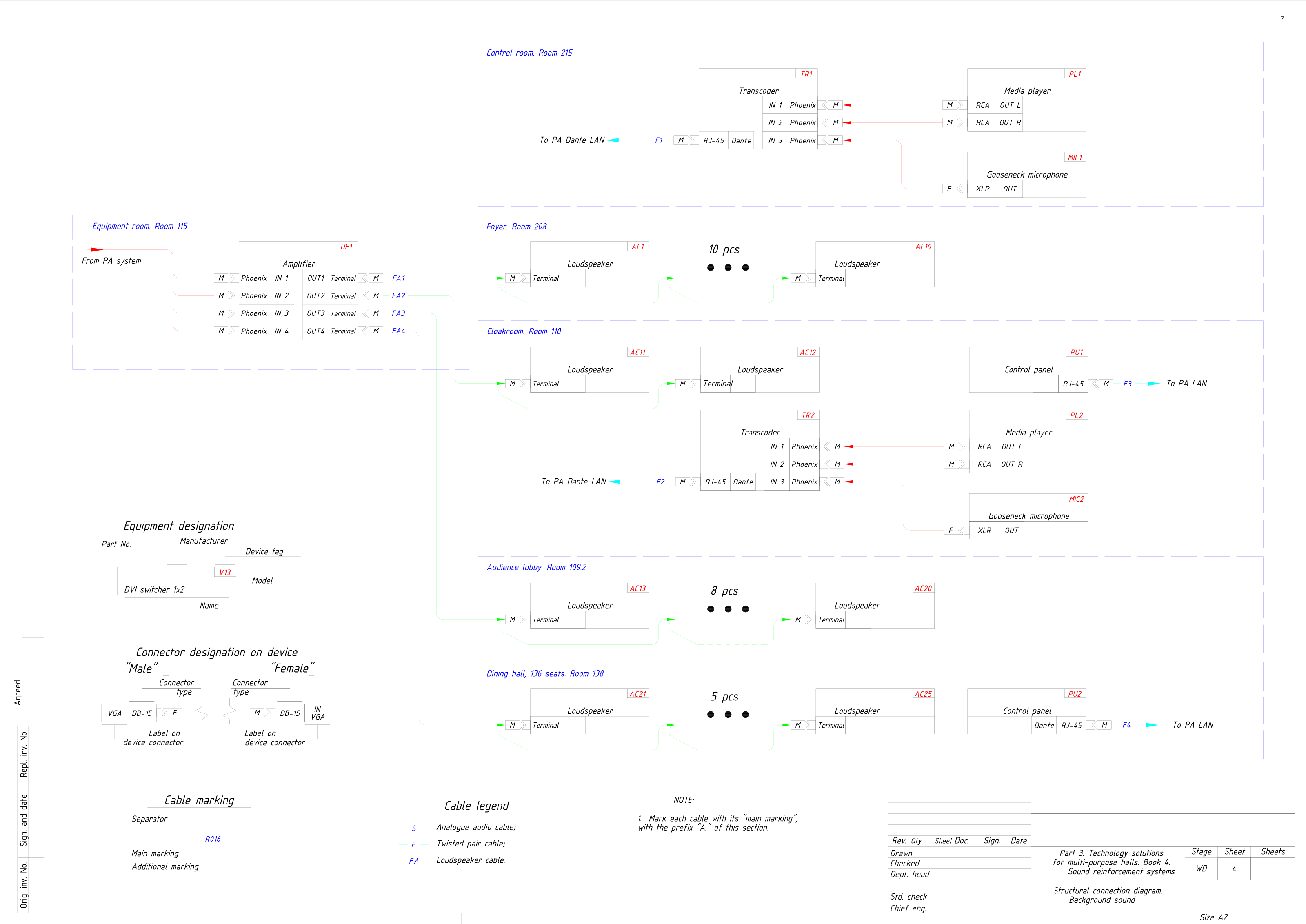
Background music and announcements for the foyer, the cloakroom, the audience lobby and a 136-seat dining hall of RC‑08: one four-channel 100 V amplifier, loudspeaker zones, Dante transcoders for local players and microphones, and control panels on the network.

All 9 sheets of RC-08, PDF (303 KB)
Structural connection diagram, background sound and announcements: a working drawing of project RC-08 with device tags, connectors and numbered cables
Sheet 4 — Background sound and announcementsRC-08 · A2 · anonymised
14Talk to us

Share your venue plans.

Send venue plans, zone names, partition modes and the events you need to support.