Sheet 09 — Control rooms & command centres
Solution 09 · Control rooms & command centres

Give every operator the right view.

Bring operational information onto a shared wall, give authorised operators access to selected computers and share an approved briefing view with remote teams. Choose the workflow, then define the sources, permissions and recovery requirements.

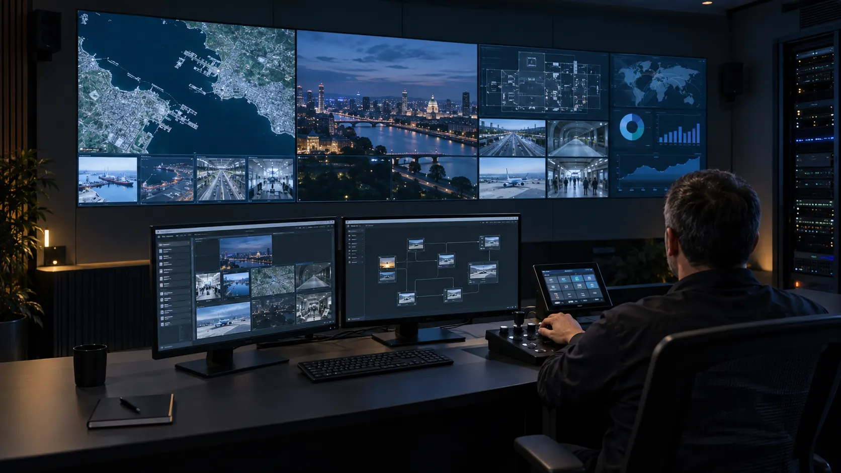
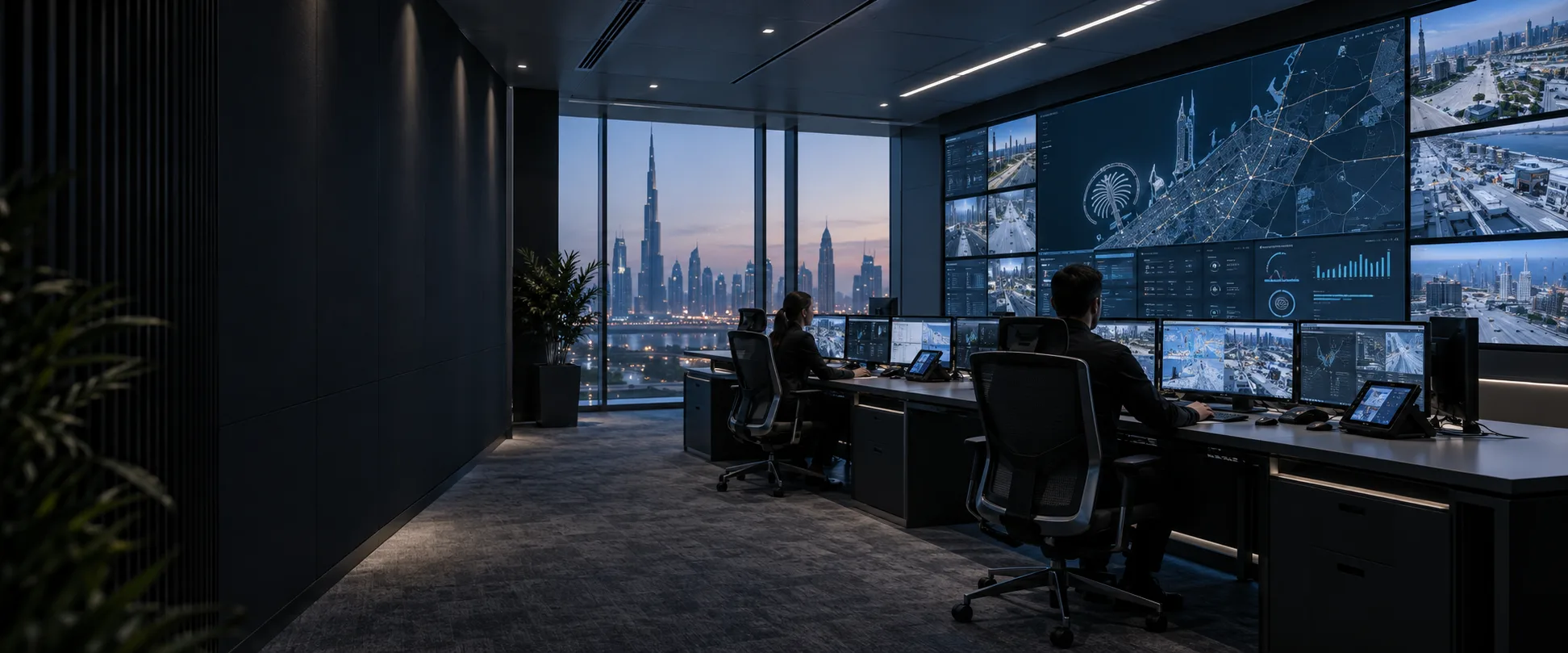
Concept visualisation of a modern Dubai control room with operator desks and a large video wall
Fig. 09.0 — Control rooms & command centres
01Overview

Start with the decisions people need to make.

The wall gives the team a common picture. Desk displays carry the detail each operator needs. Changing a wall layout, controlling a source computer and sharing information in a call are separate functions, with separate permissions.

We define the source list, operator tasks and routine, incident and briefing layouts before selecting the display and signal system. Existing operational applications remain under their owners’ control. Cameras and video management systems come from the client’s security contractor; security camera supply and installation are outside this scope.

Reference configurations · project selection and system tests required. The quantities below describe design examples. They do not establish tested capacity, completed installations or continuous availability. These examples use one desk monitor per operator; regulated security rooms and tasks requiring multiple monitors need a revised design.

Radio, emergency telephony, process control logic and safety systems remain separate systems. An AV wall does not replace them.

CraftWall for sources, scenes and operator control.

Our CraftWall video wall software runs on a local Linux server with GPU processing. Operators use a browser to arrange source windows, save scenes and recall the view needed for routine work or an incident.

Explore CraftWall
CraftWall for sources, scenes and operator control.
Product functionHow it can serve the roomProject boundary
Mixed sourcesCombine video streams, NDI, web dashboards, documents and remote desktops on the wallConfirm each source format, access method and server load
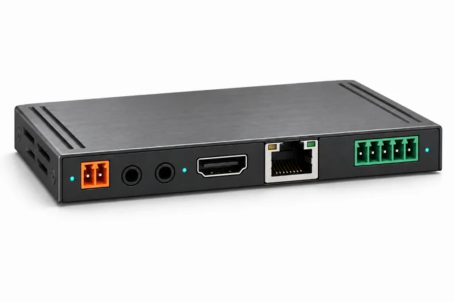
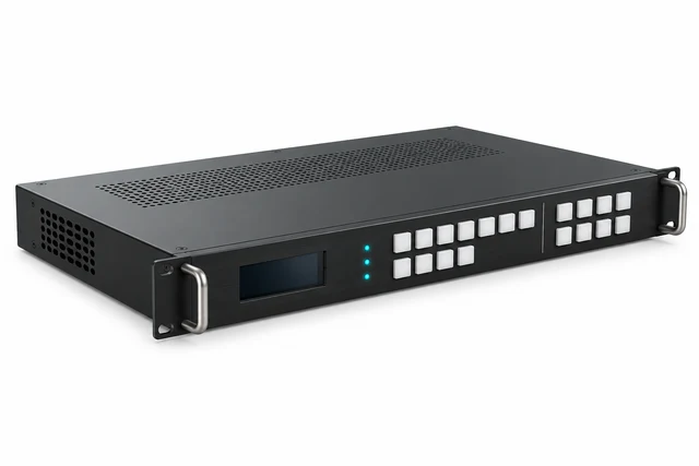
HDMI and SDI captureBring approved physical video feeds into the software compositorThe selected capture hardware must expose a compatible Linux V4L2 device; verify every simultaneous input
Scenes and display surfacesSave window geometry and grid layouts; arrange LCD or LED surfacesGPU outputs and the pixel map determine the physical display configuration
Interactive web, RDP and VNCUse the operator's keyboard and mouse inside a permitted source windowThis requires approved network sessions; it does not establish physical USB-KVM routing or exclusive control of a shared PC
Alarms and schedulesSelect a scene from an agreed HTTP event or schedule; return after an alarm while respecting a manual scene choiceConfigure and test the event interface; third-party connectors are separate scope
Source recovery and standbyRestore failed sources and saved state; use a second server where hot standby is specifiedStandby requires a complete additional signal path and measured recovery tests; it is outside these base configurations
Local deployment and rolesUse a local installation, offline licensing and administrator, operator and viewer rolesValidate identity integration, detailed permissions and the network needs of each source

CraftWall also includes a read-only SCADA visualisation module and video analytics. Connecting process tags, configuring analysis and allocating server resources are additional project work; they are not automatically included in these reference configurations.

The software licence is per server, without licence limits on the number of displays, sources, operators or canvases. Hardware resources still limit simultaneous operation. Confirm the selected release, licence terms and server configuration during selection.

For CR-01 and CR-02, CraftWall is an alternative implementation of the wall compositor. CR-02 retains its separate AV/KVM routing and access controller. For CR-03, demonstrate the independent outgoing programme and its content restrictions before selecting the compositor; support for several display surfaces alone does not prove this meeting workflow.
02Where it is used06 environments

Real environments, real priorities.

Who works in each kind of space, what they work with and what matters most to them.

Application register
No.EnvironmentWho uses itWork and contentWhat matters mostTypical systems
A01Network operations centreService operatorsCompare service dashboards and incident ticketsReadable data and agreed source ownershipCR-01 shared overview or CR-02 KVM access
A02Utility dispatch roomDispatchers and supervisorsReview authorised operational client displaysApproved interfaces and clear control permissionsCR-01 or CR-02, subject to OT review
A03Transport operations roomTraffic and logistics operatorsReview maps, status and authorised videoSource identity and readable incident layoutsCR-01 or CR-02
A04Campus operations roomDuty staffReview facility information and approved security viewsBoundaries with the existing security systemCR-01, revised for applicable security-room requirements
A05Industrial monitoring roomProcess and maintenance staffCompare approved HMI and maintenance displaysDefined USB policy and no unapproved network linksCR-02 after application and security validation
A06Situation and crisis centreDuty officers and meeting participantsBrief local and remote teamsApproved outgoing information and clear two-way speechCR-03 hybrid briefing
03Typical configurations

Three starting points, compared.

Choose the workflow closest to your brief. Compare its scope, interfaces and operating limits before selecting equipment.

Compare all 3 configurations
Configuration

Shared operational overview

CR-01

Keep four agreed sources visible while two operators work locally. Reference design; project validation required.

Explore CR-01

Authorised KVM operations

CR-02

Give four operators controlled access to six PCs, with two selected feeds on the wall. Reference design; permissions and routing validation required.

Explore CR-02

Hybrid situation briefing

CR-03

Share approved briefing content and speech with a remote team. Reference design; independent output and call validation required.

Explore CR-03
Main task

See agreed information together

Work on authorised source computers from operator desks

Discuss selected information with remote participants

Example operators

Two local operators

Four KVM operator positions

Two technical positions plus a meeting area sized separately

Information sources

Four client PCs

Six source PCs available for selection

Six client PCs plus the incoming call view

Simultaneous wall inputs

Four captured sources

Two selected sources through two wall receivers

Six information sources and one call-return input

Shared display

Four LCD panels in a 2 × 2 wall

Four LCD panels in a 2 × 2 wall

One LED display package sized to the content

Desk access

Operators use their own PCs; two of the four sources

One selected computer per desk, with controlled USB ownership

Operators use their own PCs; two of the six sources

Layouts

Manual routine and incident presets

Presets using the two currently routed wall inputs

Separate local-wall and outgoing-briefing layouts

Remote meeting

Outside base scope

Outside base scope

One camera, two microphone zones and conferencing audio

Availability

One processing path; specified power protection

One processor, routing controller and network path

One processor, LED path and conferencing PC

Status

Reference design; project validation required

Reference design; permissions and routing validation required

Reference design; independent output and call validation required

Shared operational overview

CR-01

Keep four agreed sources visible while two operators work locally. Reference design; project validation required.

Explore CR-01
Main task
See agreed information together
Example operators
Two local operators
Information sources
Four client PCs
Simultaneous wall inputs
Four captured sources
Shared display
Four LCD panels in a 2 × 2 wall
Desk access
Operators use their own PCs; two of the four sources
Layouts
Manual routine and incident presets
Remote meeting
Outside base scope
Availability
One processing path; specified power protection
Status
Reference design; project validation required

Authorised KVM operations

CR-02

Give four operators controlled access to six PCs, with two selected feeds on the wall. Reference design; permissions and routing validation required.

Explore CR-02
Main task
Work on authorised source computers from operator desks
Example operators
Four KVM operator positions
Information sources
Six source PCs available for selection
Simultaneous wall inputs
Two selected sources through two wall receivers
Shared display
Four LCD panels in a 2 × 2 wall
Desk access
One selected computer per desk, with controlled USB ownership
Layouts
Presets using the two currently routed wall inputs
Remote meeting
Outside base scope
Availability
One processor, routing controller and network path
Status
Reference design; permissions and routing validation required

Hybrid situation briefing

CR-03

Share approved briefing content and speech with a remote team. Reference design; independent output and call validation required.

Explore CR-03
Main task
Discuss selected information with remote participants
Example operators
Two technical positions plus a meeting area sized separately
Information sources
Six client PCs plus the incoming call view
Simultaneous wall inputs
Six information sources and one call-return input
Shared display
One LED display package sized to the content
Desk access
Operators use their own PCs; two of the six sources
Layouts
Separate local-wall and outgoing-briefing layouts
Remote meeting
One camera, two microphone zones and conferencing audio
Availability
One processor, LED path and conferencing PC
Status
Reference design; independent output and call validation required

Reference configurations. Example quantities require project selection, compatibility checks and system acceptance tests. Input counts describe distinct received signals. Repeating a source in several windows does not increase the number of independent sources. All three examples require a project-specific equipment and licence schedule.

Follow the signal path for your configuration.

CR-01

Shared operational overview

Reference design; project validation required

Two operators continue working on their own computers while the team sees four agreed information sources on a shared wall. Their two PCs are included in the four-source count.

CR-01 · Shared operational overview

Keep four agreed sources visible while two operators work locally.

Signal flow

Signal flow. Devices, connections and conditions follow the drawing.Open SVG ↗
CR-01 · Signal flowReference design. Four information PCs feed four capture channels and four LCD outputs. Two local operator positions use two of those same PCs. Layout commands and status use a separate management network. No KVM or processor redundancy. Reference design, not a site plan. Rack, 2 PDU, wall mount and cable/PSU sets: separate BOQ lines. UPS does not duplicate the compositor. No switched KVM. Repeated device identifiers refer to the same equipment across views. Equipment illustrations are schematic; labels define quantities.{"sourceHash":"d57319bb4cab516c8e190b53fba01a7c97740a3bcae2f27a3c450541b936a905","view":"signal","nodes":["SRC","PROC","WALL","DESK"],"edges":["L01","L02","L03","L04"]}PIXEL COMMAND SOLUTIONS / CR-01 / SIGNAL FLOWSignal flowREFERENCE DESIGN · PROJECT VALIDATION REQUIREDSRC → PROC: 4 HDMI feeds; 1080p60 assumed4 HDMI feedsPROC → WALL: 4 separate panel feeds4 separate panel feedsSRC → DESK: 2 additional local display outputs2 additional localdisplay outputsDESK → SRC: local keyboard and mouse USBlocal keyboard andmouse USB4 x source PCs S1 and S2 are the local operator PCsSRC4 x source PCs1 x wall compositor 4 capture channels / 4 panel outputsPROC1 x wall compositor4 x LCD panels 2 by 2; FHD per panel assumedWALL4 x LCD panels2 x local operator sets monitor + keyboard + mouse; no extra PCsDESK2 x local operatorsetsVideo / LED dataUSB / KVM
Devices, connections & design conditions 4 connections
  • Four HDMI sources feed four capture channels.
  • Four separate outputs drive the LCD panels.
  • Two local desks use two of those source PCs; layout control is separate.
SRC
4 x source PCs S1 and S2 are the local operator PCs
PROC
1 x wall compositor 4 capture channels / 4 panel outputs
WALL
4 x LCD panels 2 by 2; FHD per panel assumed
DESK
2 x local operator sets monitor + keyboard + mouse; no extra PCs
  1. SRC → PROC4 HDMI feeds; 1080p60 assumed
  2. PROC → WALL4 separate panel feeds
  3. SRC → DESK2 additional local display outputs
  4. DESK → SRClocal keyboard and mouse USB

Reference design, not a site plan. Rack, 2 PDU, wall mount and cable/PSU sets: separate BOQ lines. UPS does not duplicate the compositor. No switched KVM.

Control & status

Signal flow. Devices, connections and conditions follow the drawing.Open SVG ↗
CR-01 · Control & statusReference design. Four information PCs feed four capture channels and four LCD outputs. Two local operator positions use two of those same PCs. Layout commands and status use a separate management network. No KVM or processor redundancy. Reference design, not a site plan. Rack, 2 PDU, wall mount and cable/PSU sets: separate BOQ lines. UPS does not duplicate the compositor. No switched KVM. Repeated device identifiers refer to the same equipment across views. Equipment illustrations are schematic; labels define quantities.{"sourceHash":"d57319bb4cab516c8e190b53fba01a7c97740a3bcae2f27a3c450541b936a905","view":"control","nodes":["PROC","WALL","PANEL","NET","UPS"],"edges":["L05","L06","L07","L08"]}PIXEL COMMAND SOLUTIONS / CR-01 / CONTROL & STATUSControl & statusREFERENCE DESIGN · PROJECT VALIDATION REQUIREDPANEL ↔ NET: IP: commands / active stateIP: commands / activestateNET ↔ PROC: IP: presets / input loss / display statusIP: presets / inputloss / display statusNET ↔ WALL: IP: panel control and statusIP: panel control andstatusUPS → NET: power status; mains circuits omittedpower status1 x wall compositor 4 capture channels / 4 panel outputsPROC1 x wall compositor4 x LCD panels 2 by 2; FHD per panel assumedWALL4 x LCD panels1 x layout panel authorised scene userPANEL1 x layout panel1 x management switch 16 ports; 7 used + 1 serviceNET1 x management switch1 x UPS system source, desk, control and wall loads sized separatelyUPS1 x UPS systemControl / status
Devices, connections & design conditions 4 connections
  • Four HDMI sources feed four capture channels.
  • Four separate outputs drive the LCD panels.
  • Two local desks use two of those source PCs; layout control is separate.
PROC
1 x wall compositor 4 capture channels / 4 panel outputs
WALL
4 x LCD panels 2 by 2; FHD per panel assumed
PANEL
1 x layout panel authorised scene user
NET
1 x management switch 16 ports; 7 used + 1 service
UPS
1 x UPS system source, desk, control and wall loads sized separately
  1. PANEL ↔ NETIP: commands / active state
  2. NET ↔ PROCIP: presets / input loss / display status
  3. NET ↔ WALLIP: panel control and status
  4. UPS → NETpower status; mains circuits omitted

Reference design, not a site plan. Rack, 2 PDU, wall mount and cable/PSU sets: separate BOQ lines. UPS does not duplicate the compositor. No switched KVM.

Typical architecture · not a project drawing

Workflow, boundaries and intended result

Composition

Four source PCs, two desk monitor/keyboard/mouse sets, one compositor with four simultaneous capture channels and four panel outputs, four LCD panels, one layout-control panel and one management switch. Mounts, rack distribution, cabling and a separately sized UPS system complete the example.

Layouts and operation

A routine preset shows all four sources. An incident preset enlarges the selected source while retaining agreed context. Operators work on their local applications; the authorised layout user controls wall placement.

Boundaries

Remote KVM switching, automatic alarm integration, recording and conferencing are outside this configuration. Two operator PCs need independent desktop and wall-feed outputs. Displaying a client application does not imply direct access to its underlying service or camera streams.

Intended result

Operators can read the selected information from the agreed positions, recall layouts and identify a lost source without interrupting local computer work.

Example equipment for CR-01

Example quantities for the selected configuration; final selection follows the approved design. A catalogue listing does not confirm stock, delivery time or complete-system compatibility.

LCD wall and mounting
Four panels for CR-01 or CR-02

Project selection; verify duty rating, geometry and service access

Wall composition and capture
1 compositor; 4 capture inputs / 4 panel outputs

Video processing; verify simultaneous resources and licences

Operator equipment and controls
2 local desk sets; 1 wall-layout panel

Project selection against roles, application and USB policy

Power and installation
UPS system, racks, PDU, mounts and cabling

Separate load, autonomy, heat and installation schedules

CR-02

Authorised KVM operations

Reference design; permissions and routing validation required

Four operators select from six source PCs. Each desk receives one selected picture and can request keyboard and mouse control where its role permits.

CR-02 · Authorised KVM operations

Give four operators controlled access to six PCs, with two selected feeds on the wall.

Signal flow

Signal flow. Devices, connections and conditions follow the drawing.Open SVG ↗
CR-02 · Signal flowReference design. Six source encoders feed four desk receivers and two wall receivers through one managed network. The wall accepts two simultaneous sources. A separate controller grants and verifies exclusive USB ownership. No processor or switch failover is included. Reference design. Dashed links are logical control sessions over the same switch. SIX-WALL option: add 4 wall receivers AND 4 capture channels; total 16 endpoints. One processor, controller and switch. Infrastructure is counted separately. Repeated device identifiers refer to the same equipment across views. Equipment illustrations are schematic; labels define quantities.{"sourceHash":"02f743712b7dbea776fa47f08612e19955b7ba9166f952b2db46046f881ec809","view":"signal","nodes":["SRC","ENC","NET","RX","HUB","DESK","WRX","PROC","WALL"],"edges":["L01","L02","L03","L04","L05","L06","L07","L08","L09","L10"]}PIXEL COMMAND SOLUTIONS / CR-02 / SIGNAL FLOWSignal flowREFERENCE DESIGN · PROJECT VALIDATION REQUIREDSRC → ENC: 6 HDMI source feeds6 × HDMIENC ↔ SRC: USB: source host to endpoint DEVICEUSB host ↔DEVICEENC ↔ NET: 1 GbE per endpoint: media / USB / control1 GbE perendpointNET ↔ RX: 4 selected AV and authorised USB routes4 × AV + USBRX → DESK: 4 HDMI desk feeds4 × HDMIRX ↔ HUB: USB HOSTUSB HOSTHUB ↔ DESK: keyboard / mouse USBKeyboard /mouseNET → WRX: 2 selected video streams2 videostreamsWRX → PROC: 2 HDMI inputs2 × HDMIPROC → WALL: 4 panel outputs4 panel outputs6 x source PCs HDMI out + USB host; source LAN stays separateSRC6 x source PCs6 x AV/KVM encoders USB DEVICE port connects to source PCENC6 x AV/KVM encoders1 x managed AV/control switch 48 ports; 24 used + 1 service; multicast + USBNET1 x managed AV/controlswitch4 x desk receivers HDMI out; USB HOST to peripheralsRX4 x desk receivers4 x powered USB hubs one per desk; approved keyboard / mouse onlyHUB4 x powered USB hubs4 x operator desk sets one monitor and one selected PC per deskDESK4 x operator desk sets2 x wall receivers video only; no USB route or peripheralWRX2 x wall receivers1 x wall compositor 2 capture channels / 4 panel outputsPROC1 x wall compositor4 x LCD panels 2 by 2; TWO sources at onceWALL4 x LCD panelsVideo / LED dataUSB / KVMNetwork / data
Devices, connections & design conditions 10 connections
  • Six encoders feed four desk receivers and two wall receivers.
  • The wall receives two sources at once.
  • The controller confirms the video route and exclusive USB ownership before granting control.
SRC
6 x source PCs HDMI out + USB host; source LAN stays separate
ENC
6 x AV/KVM encoders USB DEVICE port connects to source PC
NET
1 x managed AV/control switch 48 ports; 24 used + 1 service; multicast + USB
RX
4 x desk receivers HDMI out; USB HOST to peripherals
HUB
4 x powered USB hubs one per desk; approved keyboard / mouse only
DESK
4 x operator desk sets one monitor and one selected PC per desk
WRX
2 x wall receivers video only; no USB route or peripheral
PROC
1 x wall compositor 2 capture channels / 4 panel outputs
WALL
4 x LCD panels 2 by 2; TWO sources at once
  1. SRC → ENC6 HDMI source feeds
  2. ENC ↔ SRCUSB: source host to endpoint DEVICE
  3. ENC ↔ NET1 GbE per endpoint: media / USB / control
  4. NET ↔ RX4 selected AV and authorised USB routes
  5. RX → DESK4 HDMI desk feeds
  6. RX ↔ HUBUSB HOST
  7. HUB ↔ DESKkeyboard / mouse USB
  8. NET → WRX2 selected video streams
  9. WRX → PROC2 HDMI inputs
  10. PROC → WALL4 panel outputs

Reference design. Dashed links are logical control sessions over the same switch. SIX-WALL option: add 4 wall receivers AND 4 capture channels; total 16 endpoints. One processor, controller and switch. Infrastructure is counted separately.

Control & status

Signal flow. Devices, connections and conditions follow the drawing.Open SVG ↗
CR-02 · Control & statusReference design. Six source encoders feed four desk receivers and two wall receivers through one managed network. The wall accepts two simultaneous sources. A separate controller grants and verifies exclusive USB ownership. No processor or switch failover is included. Reference design. Dashed links are logical control sessions over the same switch. SIX-WALL option: add 4 wall receivers AND 4 capture channels; total 16 endpoints. One processor, controller and switch. Infrastructure is counted separately. Repeated device identifiers refer to the same equipment across views. Equipment illustrations are schematic; labels define quantities.{"sourceHash":"02f743712b7dbea776fa47f08612e19955b7ba9166f952b2db46046f881ec809","view":"control","nodes":["NET","PROC","WALL","UI","PANEL","CTRL","UPS"],"edges":["L11","L12","L13","L14","L15","L16"]}PIXEL COMMAND SOLUTIONS / CR-02 / CONTROL & STATUSControl & statusREFERENCE DESIGN · PROJECT VALIDATION REQUIREDUI ↔ CTRL: authenticated requests / confirmed stateauthenticated requests/ confirmed statePANEL ↔ CTRL: layout request / active statelayout request / activestateCTRL ↔ NET: IP via switch: video route and USB pairing; verify before grantIP via switch: videoroute and USB pairingCTRL ↔ PROC: IP via switch: presets / statusIP via switch: presets/ statusNET ↔ WALL: IP: panel status / controlIP: panel status /controlUPS → NET: IP statusIP status1 x managed AV/control switch 48 ports; 24 used + 1 service; multicast + USBNET1 x managed AV/controlswitch1 x wall compositor 2 capture channels / 4 panel outputsPROC1 x wall compositor4 x LCD panels 2 by 2; TWO sources at onceWALL4 x LCD panels4 x operator access panels login; request; source / owner / grant statusUI4 x operator accesspanels1 x wall-layout panel wall rights do not grant USB controlPANEL1 x wall-layout panel1 x routing and access controller roles; one USB owner per PC; licences includedCTRL1 x routing and accesscontroller1 x UPS system all agreed loads; power status via switchUPS1 x UPS systemControl / status
Devices, connections & design conditions 6 connections
  • Six encoders feed four desk receivers and two wall receivers.
  • The wall receives two sources at once.
  • The controller confirms the video route and exclusive USB ownership before granting control.
NET
1 x managed AV/control switch 48 ports; 24 used + 1 service; multicast + USB
PROC
1 x wall compositor 2 capture channels / 4 panel outputs
WALL
4 x LCD panels 2 by 2; TWO sources at once
UI
4 x operator access panels login; request; source / owner / grant status
PANEL
1 x wall-layout panel wall rights do not grant USB control
CTRL
1 x routing and access controller roles; one USB owner per PC; licences included
UPS
1 x UPS system all agreed loads; power status via switch
  1. UI ↔ CTRLauthenticated requests / confirmed state
  2. PANEL ↔ CTRLlayout request / active state
  3. CTRL ↔ NETIP via switch: video route and USB pairing; verify before grant
  4. CTRL ↔ PROCIP via switch: presets / status
  5. NET ↔ WALLIP: panel status / control
  6. UPS → NETIP status

Reference design. Dashed links are logical control sessions over the same switch. SIX-WALL option: add 4 wall receivers AND 4 capture channels; total 16 endpoints. One processor, controller and switch. Infrastructure is counted separately.

Typical architecture · not a project drawing

Workflow, boundaries and intended result

Composition

Six source PCs, six source encoders, four desk receivers, two wall receivers, four desk monitor/keyboard/mouse sets with powered USB hubs, four operator access panels, one routing and access controller, one wall-layout panel, one compositor with two capture channels and four panel outputs, four LCD panels and one managed AV/control switch. Power and installation infrastructure are counted separately.

Layouts and operation

The controller grants or rejects a control request and indicates the selected source, current owner and connection status. The proposed policy allows one controlling desk per source PC; other authorised viewers may watch without USB control. The two wall receivers select two of the six computers. A routine layout shows both; an incident layout enlarges one of them.

Boundaries

The base wall receives two sources simultaneously, not six. Showing all six requires four additional wall receivers and four additional capture channels, or a separately validated alternative ingest design. KVM permissions and exclusive ownership require a validated control application; they do not follow from purchasing endpoints. The base peripheral set is keyboard and mouse. Touch, headsets, cameras, removable storage and other USB classes require separate approval and testing. The baseline has one monitor per desk and no processor or network failover.

Intended result

Each operator reaches permitted computers, sees whether control has been granted and can release it for another operator. A wall route never grants USB control to the wall.

Example equipment for CR-02

Example quantities for the selected configuration; final selection follows the approved design. A catalogue listing does not confirm stock, delivery time or complete-system compatibility.

LCD wall and mounting
Four panels for CR-01 or CR-02

Project selection; verify duty rating, geometry and service access

Wall composition and capture
1 compositor; 2 capture inputs / 4 panel outputs

Video processing; verify simultaneous resources and licences

AV/KVM endpoints and network
Six encoders and six receivers for CR-02

AV over IP and signal extension; USB capability needs explicit selection

Operator equipment and controls
4 desk sets and access panels; 1 routing controller and 1 wall-layout panel

Project selection against roles, application and USB policy

Power and installation
UPS system, racks, PDU, mounts and cabling

Separate load, autonomy, heat and installation schedules

CR-03

Hybrid situation briefing

Reference design; independent output and call validation required

Two technical operators prepare information for a local meeting and one remote call. Their PCs form part of the six information sources; a separate conferencing PC runs the call.

CR-03 · Hybrid situation briefing

Share approved briefing content and speech with a remote team.

Video & data

Signal flow. Devices, connections and conditions follow the drawing.Open SVG ↗
CR-03 · Video & dataReference design. Six information sources and one call return feed a compositor. The local LED wall and outgoing programme are independently composed. The outgoing programme excludes the call return. Camera and programme use separate USB captures. DSP sends room microphones to the call and uses the incoming audio as AEC reference and room playback. Reference design, not a completed installation. Independent composition and camera + external content workflow require FAT. Power, mounts, rack, 2 PDU and cable/PSU sets are separate BOQ lines. No failover. Repeated device identifiers refer to the same equipment across views. Equipment illustrations are schematic; labels define quantities.{"sourceHash":"92ddf731337343df6365a8c47071894e541eae9bce1160441ccb43c4d731a606","view":"signal","nodes":["SRC","DESK","PROC","LED","SHARE","UC","SERVICE","CAM","CAP"],"edges":["L01","L02","L03","L04","L05","L06","L07","L08","L09","L10"]}PIXEL COMMAND SOLUTIONS / CR-03 / VIDEO & DATAVideo & dataREFERENCE DESIGN · PROJECT VALIDATION REQUIREDSRC → PROC: 6 HDMI: C1 to C66 × HDMI ·C1–C6SRC → DESK: 2 separate local display outputs2 localvideooutputsDESK → SRC: local keyboard and mouse USBUSB keyboard / mousePROC → LED: O1 WALL; LED pixel map by designO1 · WALLPROC → SHARE: O2 SHARE; independent 1080p30 programmeO2 · SHARE 1080p30SHARE → UC: USB video: approved contentUSB approvedcontentUC → PROC: HDMI: C7 call return; separate from UC local UIHDMI · C7 call returnCAM → CAP: SDISDICAP → UC: USB camera videoUSB camera videoUC ↔ SERVICE: IP: meeting media and signallingIP meetingmedia +signalling6 x information PCs includes the two local technical PCs; silent feedsSRC6 x information PCs2 x local operator sets monitor + keyboard + mouse; no extra PCsDESK2 x local operatorsets1 x compositor 7 capture channels / 2 independent output programmesPROC1 x compositor1 x LED display package sender + receiving cards + surface + PSULED1 x LED displaypackage1 x HDMI-to-USB capture SHARE output only; excludes C7 call returnSHARE1 x HDMI-to-USBcapture1 x conferencing PC set own local monitor; camera + content + USB audioUC1 x conferencing PCset1 x client conferencing service client network / WAN; outside AV management LANSERVICE1 x clientconferencing service1 x PTZ camera SDI video; IP preset controlCAM1 x PTZ camera1 x SDI-to-USB capture camera input; selected USB formatCAP1 x SDI-to-USB captureVideo / LED dataUSB / KVMNetwork / data
Devices, connections & design conditions 10 connections
  • Six information feeds and one call return enter the compositor.
  • The independent SHARE programme excludes the call return.
  • Room microphones feed the call; call return feeds the room and AEC reference.
SRC
6 x information PCs includes the two local technical PCs; silent feeds
DESK
2 x local operator sets monitor + keyboard + mouse; no extra PCs
PROC
1 x compositor 7 capture channels / 2 independent output programmes
LED
1 x LED display package sender + receiving cards + surface + PSU
SHARE
1 x HDMI-to-USB capture SHARE output only; excludes C7 call return
UC
1 x conferencing PC set own local monitor; camera + content + USB audio
SERVICE
1 x client conferencing service client network / WAN; outside AV management LAN
CAM
1 x PTZ camera SDI video; IP preset control
CAP
1 x SDI-to-USB capture camera input; selected USB format
  1. SRC → PROC6 HDMI: C1 to C6
  2. SRC → DESK2 separate local display outputs
  3. DESK → SRClocal keyboard and mouse USB
  4. PROC → LEDO1 WALL; LED pixel map by design
  5. PROC → SHAREO2 SHARE; independent 1080p30 programme
  6. SHARE → UCUSB video: approved content
  7. UC → PROCHDMI: C7 call return; separate from UC local UI
  8. CAM → CAPSDI
  9. CAP → UCUSB camera video
  10. UC ↔ SERVICEIP: meeting media and signalling

Reference design, not a completed installation. Independent composition and camera + external content workflow require FAT. Power, mounts, rack, 2 PDU and cable/PSU sets are separate BOQ lines. No failover.

Audio & return paths

Signal flow. Devices, connections and conditions follow the drawing.Open SVG ↗
CR-03 · Audio & return pathsReference design. Six information sources and one call return feed a compositor. The local LED wall and outgoing programme are independently composed. The outgoing programme excludes the call return. Camera and programme use separate USB captures. DSP sends room microphones to the call and uses the incoming audio as AEC reference and room playback. Reference design, not a completed installation. Independent composition and camera + external content workflow require FAT. Power, mounts, rack, 2 PDU and cable/PSU sets are separate BOQ lines. No failover. Repeated device identifiers refer to the same equipment across views. Equipment illustrations are schematic; labels define quantities.{"sourceHash":"92ddf731337343df6365a8c47071894e541eae9bce1160441ccb43c4d731a606","view":"audio","nodes":["UC","MIC","DSP","AMP","SPK"],"edges":["L11","L12","L13","L14","L15","L16"]}PIXEL COMMAND SOLUTIONS / CR-03 / AUDIO & RETURN PATHSAudio & return pathsREFERENCE DESIGN · PROJECT VALIDATION REQUIREDMIC → DSP: 2 balanced mic inputs2 balanced mic inputsDSP → UC: USB send: mics after AEC; no return audioUSB send: mics afterAECUC → DSP: USB receive: call returnUSB receive: callreturnDSP → AMP: mono line output: return mixmono line output:return mixAMP → SPK: speaker circuit: matched loadspeaker circuit:matched loadDSP → DSP: internal AEC reference: actual room return mixinternal AEC reference:actual room return mix1 x conferencing PC set own local monitor; camera + content + USB audioUC1 x conferencing PCset2 x wired microphone zones initial layout; room coverage to be testedMIC2 x wired microphonezones1 x AEC audio processor mic send / call return / AEC referenceDSP1 x AEC audioprocessor1 x amplifier selected line and load typeAMP1 x amplifier2 x room loudspeakers call return only; no local mic reinforcementSPK2 x room loudspeakersAudioUSB / KVM
Devices, connections & design conditions 6 connections
  • Six information feeds and one call return enter the compositor.
  • The independent SHARE programme excludes the call return.
  • Room microphones feed the call; call return feeds the room and AEC reference.
UC
1 x conferencing PC set own local monitor; camera + content + USB audio
MIC
2 x wired microphone zones initial layout; room coverage to be tested
DSP
1 x AEC audio processor mic send / call return / AEC reference
AMP
1 x amplifier selected line and load type
SPK
2 x room loudspeakers call return only; no local mic reinforcement
  1. MIC → DSP2 balanced mic inputs
  2. DSP → UCUSB send: mics after AEC; no return audio
  3. UC → DSPUSB receive: call return
  4. DSP → AMPmono line output: return mix
  5. AMP → SPKspeaker circuit: matched load
  6. DSP → DSPinternal AEC reference: actual room return mix

Reference design, not a completed installation. Independent composition and camera + external content workflow require FAT. Power, mounts, rack, 2 PDU and cable/PSU sets are separate BOQ lines. No failover.

Control & status

Signal flow. Devices, connections and conditions follow the drawing.Open SVG ↗
CR-03 · Control & statusReference design. Six information sources and one call return feed a compositor. The local LED wall and outgoing programme are independently composed. The outgoing programme excludes the call return. Camera and programme use separate USB captures. DSP sends room microphones to the call and uses the incoming audio as AEC reference and room playback. Reference design, not a completed installation. Independent composition and camera + external content workflow require FAT. Power, mounts, rack, 2 PDU and cable/PSU sets are separate BOQ lines. No failover. Repeated device identifiers refer to the same equipment across views. Equipment illustrations are schematic; labels define quantities.{"sourceHash":"92ddf731337343df6365a8c47071894e541eae9bce1160441ccb43c4d731a606","view":"control","nodes":["PROC","LED","CAM","DSP","PANEL","NET","UPS"],"edges":["L17","L18","L19","L20","L21","L22"]}PIXEL COMMAND SOLUTIONS / CR-03 / CONTROL & STATUSControl & statusREFERENCE DESIGN · PROJECT VALIDATION REQUIREDPANEL ↔ NET: IP managementIP managementNET ↔ PROC: IP: layouts / input and output stateIP: layouts / input andoutput stateNET ↔ CAM: IP: presets / statusIP: presets / statusNET ↔ DSP: IP: audio control / statusIP: audio control /statusNET ↔ LED: IP: sender control / statusIP: sender control /statusUPS → NET: IP power statusIP power status1 x compositor 7 capture channels / 2 independent output programmesPROC1 x compositor1 x LED display package sender + receiving cards + surface + PSULED1 x LED displaypackage1 x PTZ camera SDI video; IP preset controlCAM1 x PTZ camera1 x AEC audio processor mic send / call return / AEC referenceDSP1 x AEC audioprocessor1 x layout / room panel share and mute state stay in UC app unless API is validatedPANEL1 x layout / roompanel1 x management switch 16 ports; 6 used + 1 serviceNET1 x management switch1 x UPS system agreed source, wall, control and meeting loadsUPS1 x UPS systemControl / status
Devices, connections & design conditions 6 connections
  • Six information feeds and one call return enter the compositor.
  • The independent SHARE programme excludes the call return.
  • Room microphones feed the call; call return feeds the room and AEC reference.
PROC
1 x compositor 7 capture channels / 2 independent output programmes
LED
1 x LED display package sender + receiving cards + surface + PSU
CAM
1 x PTZ camera SDI video; IP preset control
DSP
1 x AEC audio processor mic send / call return / AEC reference
PANEL
1 x layout / room panel share and mute state stay in UC app unless API is validated
NET
1 x management switch 16 ports; 6 used + 1 service
UPS
1 x UPS system agreed source, wall, control and meeting loads
  1. PANEL ↔ NETIP management
  2. NET ↔ PROCIP: layouts / input and output state
  3. NET ↔ CAMIP: presets / status
  4. NET ↔ DSPIP: audio control / status
  5. NET ↔ LEDIP: sender control / status
  6. UPS → NETIP power status

Reference design, not a completed installation. Independent composition and camera + external content workflow require FAT. Power, mounts, rack, 2 PDU and cable/PSU sets are separate BOQ lines. No failover.

Typical architecture · not a project drawing

Workflow, boundaries and intended result

Composition

Six source PCs, two desk monitor/keyboard/mouse sets, one compositor with seven simultaneous capture channels and two independently composed outputs, one LED display package, one conferencing PC with its own control monitor, one PTZ camera and SDI-to-USB capture, one HDMI-to-USB programme capture, two wired microphone zones, one echo-cancelling audio processor, one amplifier and two room loudspeakers. A control panel, management switch, conferencing service and installation/power infrastructure support the system.

Layouts and operation

The local wall can include information sources and the incoming call. A separate outgoing programme contains only sources approved for remote sharing. The call-return input is excluded from that programme. Staff preview and explicitly start or stop sharing; camera and microphone mute states remain visible.

Boundaries

The conferencing application must support a camera and an external captured content feed in the agreed workflow. Two capture devices alone do not prove this. The programme output is independently composed, not a copy of the whole wall. The base information feeds are silent; source audio, recording, additional meeting displays, remote KVM and camera tracking are separate scope. Two microphone zones and two loudspeakers are initial quantities, not a confirmed room capacity.

Intended result

Local and remote participants discuss the selected material with intelligible speech. Information on the local wall can remain private, and neither the returning call image nor its audio is sent straight back to the remote side.

Example equipment for CR-03

Example quantities for the selected configuration; final selection follows the approved design. A catalogue listing does not confirm stock, delivery time or complete-system compatibility.

Fine-pitch LED system
One complete surface, sender, receivers and power system for CR-03

Fine-pitch LED; final pixel and port map required

Wall composition and capture
1 compositor; 7 capture inputs / 2 independently composed outputs

Video processing; verify simultaneous resources and licences

Operator equipment and controls
2 local desk sets; 1 room control panel

Project selection against roles, application and USB policy

Meeting capture and microphones
CR-03 camera, two captures and two microphone zones

Microphones; camera/capture selection by tested interfaces

Meeting audio
CR-03 AEC processor, amplifier and two speakers

Audio processing, amplifiers and speakers

Power and installation
UPS system, racks, PDU, mounts and cabling

Separate load, autonomy, heat and installation schedules

05Reference architectureInteractive

How a typical system fits together.

Four layers, from the sources to the people operating the system. Select a layer to see its components and the interfaces between them.

Typical architecture · Control rooms & command centres

L2 · Selected layerProcessing & transport

How signals are routed and processed in a typical system of this kind.

Components and interfaces
  • Capture and compositionHDMI / USBHDMI capture; dedicated managed transport for video and USB; input and output licences selected together
  • AV/KVM endpoints in CR-02HDMI / USBHDMI capture; dedicated managed transport for video and USB; input and output licences selected together
Documented scope · Control rooms & command centres
  • Shared LCD or LED display and image composition.
  • Source connections and operator workstations.
  • KVM routing and operator access control in CR-02.
  • Conferencing and a separate outgoing programme in CR-03.
  • Layout controls, power planning, verification and staff training.
Prepare for the first conversation
  1. 01Room plans, wall dimensions, desk positions and service access.
  2. 02Source list with physical location, interfaces, formats, versions and content examples.
  3. 03Operator counts, shifts, tasks and required desk monitor counts.
  4. 04Who may view, control, change layouts and share information remotely.
  5. 05Required routine, incident and briefing layouts, including simultaneous source counts.
  6. 06Network, USB, IT/OT, security and conferencing policies.
  7. 07Existing equipment, power, cooling and installation constraints.
  8. 08Availability, recovery, support and growth requirements, with the project contact.
Share your control room brief
06Design parametersTypical guidance · confirmed per project

What the design has to get right.

The engineering checks behind every drawing. Rules of thumb are starting points; the project values are confirmed with the people named.

Design parameters
No.ParameterGuidanceRule of thumbConfirmed with
D01Real informationSize the wall from readable text, maps and alarmsSample-content view from each operating positionOperators and content owners
D02Independent sourcesCount distinct simultaneous signals, not just windowsInput, capture and licence scheduleAV designer and software supplier
D03Workstation taskDefine desk displays and local or remote controlSource-to-desk matrix and ergonomic layoutOperators and fit-out team
D04USB accessStart with approved keyboard/mouse devicesDevice classes, ownership, handover and refusal rulesIT/OT and source owners
D05Wall layoutsSpecify routine, incident and briefing scenesPresets with source identity and loss indicationShift supervisor
D06Remote sharingSelect information separately from the local wallOutgoing allowlist, preview and call testsInformation owner and meeting host
D07NetworkDesign multicast, management access and bandwidth togetherPort/VLAN schedule and permitted connectionsNetwork and security teams
D08Power and continuityIdentify each single point of failureProtected loads, required recovery and optional duplicate pathsOperations and electrical team
D09Service and environmentPlan access, heat, noise and continuous-duty requirementsManufacturer ratings and coordinated installation drawingsFacilities and suppliers
D10GrowthReserve usable inputs, network ports and powerExplicit expansion quantities and licence changesClient and designer
Common mistakes

And how the design process prevents them.

  1. M01

    Mistake: Calling six selectable sources six simultaneous wall inputs

    Prevention: Show the two-receiver limit in CR-02 and price expansion separately

  2. M02

    Mistake: Giving everyone a shared administrator login

    Prevention: Separate operator, supervisor and administrator actions; test denied requests

  3. M03

    Mistake: Treating a USB connection as permission to control a source

    Prevention: Validate device classes and enforce source ownership

  4. M04

    Mistake: Sharing the complete wall into a call

    Prevention: Use an independent outgoing programme that excludes the call return

  5. M05

    Mistake: Describing a UPS as processor redundancy

    Prevention: State the failed component, surviving path and measured recovery

  6. M06

    Mistake: Promising alarm automation from an available API alone

    Prevention: Confirm both systems, versions, licences and trigger behaviour

07Design referencesEditions checked per project

The references we design to.

Equipment documentation, industry guides and project requirements inform the design. Confirm applicable editions and acceptance criteria for the site.

Equipment documentation and industry guides04

  • ISO 11064 seriesProject design referenceControl-room tasks, workstation arrangement and ergonomic review; identify applicable partsCheck current edition
  • AVIXA DISCASProject design referenceImage-size assessment using actual viewing positions and contentCheck current edition
  • AVIXA audiovisual systems performance verificationProject design referenceAgree a project-specific test schedule and record resultsCheck current edition
  • Applicable site, electrical and security-system requirementsProject design referenceCoordinate with the responsible designers and security contractor before procurementCheck current edition

Local and project requirements01

  • Client IT, OT and security requirementsProject design referenceApprove source access, network connections, USB policy and remote sharingCheck current edition
08Integrations08 interfaces

Connected to the building and its IT.

The systems this solution usually exchanges signals or data with, and why. Each interface is agreed with the system owner.

  • I01

    Existing VMS and security systems

    Approved client HDMI output; other interfaces by agreement

    Show authorised views; cameras, VMS and security-system works remain with the client's contractor

  • I02

    SCADA, DCS and operational clients

    Agreed display output; approved USB in CR-02

    View or control the selected client; KVM is not proof of network isolation or safety-system suitability

  • I03

    GIS, dashboards and incident tools

    Existing client PC

    Use authorised application views without assuming a direct connector

  • I04

    Identity and access

    Selected controller accounts; directory interface only if validated

    Control source visibility, USB ownership and layout changes

  • I05

    Conferencing service

    Camera capture, programme capture, USB audio and client network

    CR-03 remote briefing; validate application behaviour, licences and sharing permission

  • I06

    Alarm automation

    Optional documented API or event interface

    Additional scope after confirming both endpoints, priority and manual override

  • I07

    Management and time services

    Approved management network and supported time/status interfaces

    Identify source loss, device condition and event times; no universal monitoring protocol assumed

  • I08

    Power and facilities

    Specified UPS status and electrical/HVAC coordination

    Protect agreed loads and plan recovery; automatic failover requires a separate design

09Equipment03 catalogue types

What a system of this kind is built from.

The catalogue types this solution usually draws on. Makes and models are selected per project, against the confirmed specification.

Open the catalogue
10Delivery

From the brief to an accepted system.

The six stages follow the selected configuration. Platform development or unconfirmed software functions require their own agreed scope and validation milestones.

Our services
  1. Stage 01

    Scope and architecture

    Agree operators, shifts, sources and simultaneous views. Record control rights, sharing boundaries and required availability. Select the configuration.

    • Operator and source brief
    • Layout and access requirements
    • Availability and sharing boundaries
  2. Stage 02

    Design and approval

    Issue wall and desk layouts, signal and control diagrams, source/permission matrices, network requirements and power/heat schedules. Define additional resilience where required.

    • Wall and desk layouts
    • Signal and permission matrices
    • Network and power requirements
  3. Stage 03

    Selection and supply

    Confirm display, compositor, endpoints, capture and licence compatibility. Validate the critical KVM or conferencing workflow before releasing the final order.

    • Agreed equipment and licences
    • Checked source interfaces
    • Validated critical workflow
  4. Stage 04

    Installation and programming

    Install and label the system, connect approved sources, configure layouts and operator rights, and set up the selected software. Where CraftWall is selected, configure its approved sources, scenes and roles; test any specified alarm or identity integration.

    • Connected and labelled sources
    • Configured layouts and controls
    • Agreed operator permissions
  5. Stage 05

    Commissioning and tests

    Run real operator tasks, denied-access checks, source changes and recovery tests. For CR-03, verify the remote picture and audio; test each duplicated path if resilience is included.

    • Operator task checks
    • Access and switching results
    • Agreed failure and recovery tests
  6. Stage 06

    Handover

    Train operators and administrators. Deliver as-built diagrams, source/permission schedules, configuration backups, test results and an agreed maintenance and recovery procedure.

    • Operator and administrator training
    • As-built diagrams and backups
    • Test and maintenance records
Documented outcomes
01

Keep four agreed sources visible while two operators work locally.

02

Give four operators controlled access to six PCs, with two selected feeds on the wall.

03

Share approved briefing content and speech with a remote team.

11Acceptance

Verify the complete workflow.

Agree the demonstration and the records before accepting the selected configuration.

CR-01

Reference design; project validation required

Read four real sources, recall routine/incident layouts and identify source loss while local work continues Verify the agreed protected loads, configuration restore and defined failure behaviour

Record supplied: Content/readability record, preset list and recovery observations Power schedule, restore record and a list of remaining single points of failure

These are planned project checks. The reference configuration has not passed physical system acceptance.

CR-02

Reference design; permissions and routing validation required

Exercise all permitted and denied source requests; contend for one PC; release control; route two wall sources independently Verify the agreed protected loads, configuration restore and defined failure behaviour

Record supplied: Role matrix, route/ownership log, USB compatibility list and measured switching results Power schedule, restore record and a list of remaining single points of failure

These are planned project checks. The reference configuration has not passed physical system acceptance.

CR-03

Reference design; independent output and call validation required

Show the local wall and a different outgoing view; change the incoming call; speak from both microphone zones and the remote endpoint Verify the agreed protected loads, configuration restore and defined failure behaviour

Record supplied: Call test record, outgoing-source allowlist and audio/video loop checks Power schedule, restore record and a list of remaining single points of failure

These are planned project checks. The reference configuration has not passed physical system acceptance.

12Inputs and FAQ

Before we begin.

What to send us, and practical answers before the project starts.

Does CR-01 let operators switch between remote computers?

No. Its operators use their own PCs and select wall layouts. CR-02 adds switched KVM access to six computers, with one selected source per operator desk.

Can CR-02 show all six computers on the wall at once?

The base design has two wall receivers and two capture channels, so it receives two selected computers at once. Six simultaneous feeds require four more receivers and four more capture channels, or another validated ingest architecture.

Can two operators control the same computer?

The proposed CR-02 policy grants control to one desk at a time. Other authorised users may view it. Ownership requests, rejection, release and supervisor transfer must be implemented and tested in the selected controller.

Will any USB device work through KVM?

The base workflow covers approved keyboards and mice. Cameras, headsets, touch devices, storage and specialist peripherals have different bandwidth, driver and security requirements. List the actual devices for compatibility testing.

What does CraftWall include in these designs?

CraftWall provides browser-based source and scene management, interactive web/RDP/VNC windows, alarm and scheduled scene changes, and source recovery. The project determines which functions are configured. Its remote-desktop control does not replace CR-02 USB-KVM routing, and CR-03 still needs a demonstrated independent outgoing programme. Hot standby requires an additional server and signal path.

What can the remote participants see and hear in CR-03?

They receive the camera and approved briefing content through the tested conferencing workflow, plus room speech. The outgoing programme excludes the call-return image and can differ from the local wall. Returning call audio is excluded from the outgoing audio mix.

What happens when equipment fails?

Each base example has a single processing path. A UPS protects agreed loads against a power interruption for its specified duration; it does not replace a failed processor or switch. Additional redundancy is designed and tested against the required failure scenarios.

Can existing security and operational systems be reused?

We assess their approved display interfaces and access rules with their owners. Cameras, VMS, process logic and safety functions remain with the responsible contractors. Regulated security rooms require a specific design; the example desk and network counts are not a compliance schedule.

13From our team’s projectsRC-08 · working drawing, anonymised

The working drawing,
as we issue it.

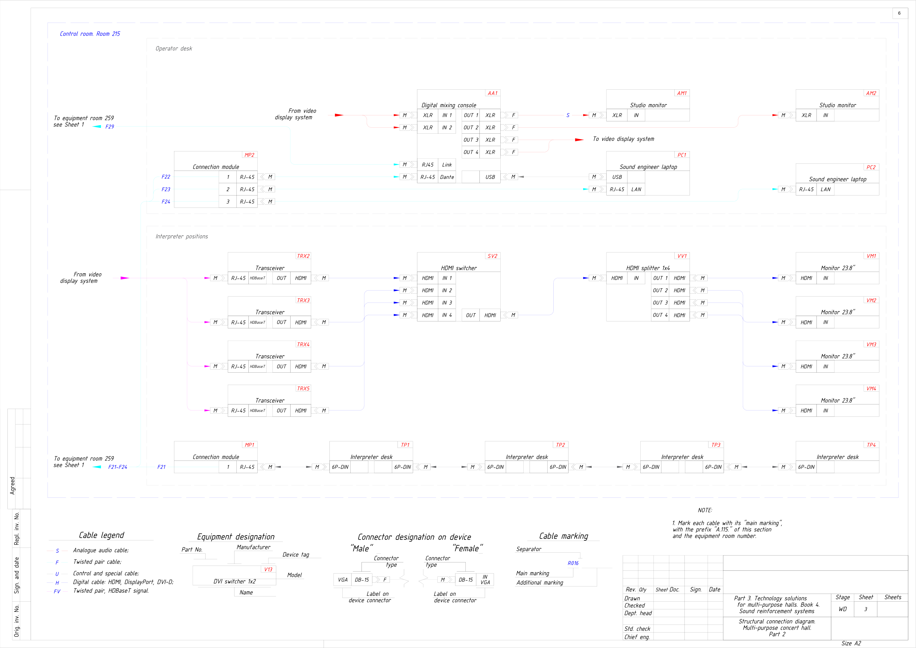
The control room of the RC‑08 hall: the operator desk with the digital mixing console, studio monitors and operator laptops on the network, and the picture from the display system distributed over HDBaseT transceivers, an HDMI switcher and a 1×4 splitter to four monitors at the interpreter positions.

All 9 sheets of RC-08, PDF (303 KB)
Structural connection diagram, multi-purpose concert hall: control room and interpreters: a working drawing of project RC-08 with device tags, connectors and numbered cables
Sheet 3 — Multi-purpose concert hall: control room and interpretersRC-08 · A2 · anonymised
14Reference complexes

Related complexes.

Documented project experience, separate from the reference designs above. Each project sheet records its own scope and outcome.

All complexes
15Talk to us

Share your control room brief.

Send the room plan, source list, operator roles and availability requirements.